ChipApex | Global Electronic Components Supplier

SEARCH
Search Product
Search Post
— IC芯片 | 连接器 | 传感器 | 被动器件 —
Search productSearch post
— IC芯片 | 连接器 | 传感器 | 被动器件 —
Consult the customer manager about the wholesale price.
consultation hotline:86-132-6715-2157
email:[email protected]
Contact the product manager for consultation. One-stop consultation is available.
Do you want a lower wholesale price? Please send us your inquiry and we will reply immediately.
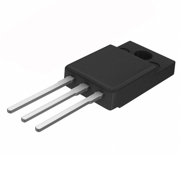
MBR1080FCT_T0_00001 is listed in the Diode Arrays range at ChipApex. The manufacturer field lists Panjit International Inc.. Its product description is DIODE ARR SCHOT 80V 10A ITO220AB. Review the specifications below when checking this part for your BOM.
The MBR1080FCT_T0_00001 is a Schottky barrier rectifier from the Panjit MBR1040FCT series, rated for 10 Amperes average forward current and 80 Volts maximum repetitive peak reverse voltage. It utilizes an ITO-220AB molded plastic case with solder-plated terminals compliant with MIL-STD-750 Method 2026. The device features a typical thermal resistance of 2°C/W and operates within a junction temperature range of -55°C to +150°C. Electrical characteristics include a maximum forward voltage of 0.9V at 5A per leg and a surge current capability of 150A.
Verify the specific part number suffix against official documentation to confirm packaging orientation and tape specifications. Ensure compliance requirements match project standards, particularly regarding RoHS 2.0 and halogen-free status. Confirm that the ITO-220AB package dimensions align with PCB layout constraints before finalizing procurement orders.
Select this component for applications requiring high current handling with low forward voltage drop. Consider the 80V reverse voltage rating for appropriate circuit protection levels. Evaluate thermal management needs based on the 2°C/W junction-to-case resistance. Verify derating curves for capacitive loads, which require a 20% current reduction.
This device belongs to the MBR1040FCT through MBR10200FCT series of 10 Ampere Schottky Barrier Rectifiers. The series offers various voltage ratings from 40V to 200V while maintaining consistent current capabilities and mechanical specifications across all variants in the lineup.
Cross-reference with other manufacturers offering 10A, 80V Schottky rectifiers in ITO-220AB packages. Verify pinout compatibility and thermal resistance values. Ensure equivalent forward voltage and reverse leakage current specifications are met for direct substitution.
The maximum forward voltage is 0.9V when measured at 5A per leg.
No, Panjit explicitly states these products are not designed or authorized for medical instruments or life-saving applications.
For capacitive loads, the current must be derated by 20% according to the datasheet specifications.
Explore related parts through Rectifiers, Diodes, Discrete Semiconductor Products, all product categories.
 MBR1080FCT_T0_00001
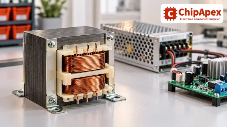
Select power transformers by input frequency, secondary VA, rectifier load, isolation, regulation and inrush. Build a clearer specification for your next RFQ.
Read More
MBR1080FCT_T0_00001 is listed in the Diode Arrays range at ChipApex. The manufacturer field lists Panjit International Inc.. Its product description is DIODE ARR SCHOT…
Read More
MBR1080FCT_T0_00001 is listed in the Diode Arrays range at ChipApex. The manufacturer field lists Panjit International Inc.. Its product description is DIODE ARR SCHOT…
Read More
MBR1080FCT_T0_00001 is listed in the Diode Arrays range at ChipApex. The manufacturer field lists Panjit International Inc.. Its product description is DIODE ARR SCHOT…
Read More
MBR1080FCT_T0_00001 is listed in the Diode Arrays range at ChipApex. The manufacturer field lists Panjit International Inc.. Its product description is DIODE ARR SCHOT…
Read More
MBR1080FCT_T0_00001 is listed in the Diode Arrays range at ChipApex. The manufacturer field lists Panjit International Inc.. Its product description is DIODE ARR SCHOT…
Read More
MBR1080FCT_T0_00001 is listed in the Diode Arrays range at ChipApex. The manufacturer field lists Panjit International Inc.. Its product description is DIODE ARR SCHOT…
Read More
MBR1080FCT_T0_00001 is listed in the Diode Arrays range at ChipApex. The manufacturer field lists Panjit International Inc.. Its product description is DIODE ARR SCHOT…
Read More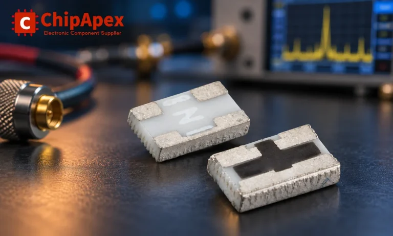
Understand RF attenuator dB values, fixed and programmable types, impedance, power limits and noise tradeoffs before choosing parts for an RF signal path.
Read More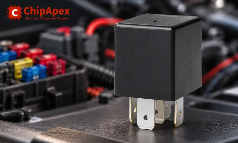
Learn the relay definition, coil and contact operation, NO and NC forms, load ratings and suppression choices. Compare mechanical, reed and solid-state types.
Read More
MBR1080FCT_T0_00001 is listed in the Diode Arrays range at ChipApex. The manufacturer field lists Panjit International Inc.. Its product description is DIODE ARR SCHOT…
Read More
See how a MEMS gyroscope measures angular rate, why its angle estimate drifts, and which range, noise, interface and temperature specs to compare.
Read More
The activity of extra discounts on wholesale prices is in full swing…
Please fill in your contact information and we will send you the latest wholesale price list.