 ChipApex | Global Electronic Components Supplier

SEARCH
Search Product
Search Post
— IC芯片 | 连接器 | 传感器 | 被动器件 —
Search productSearch post
— IC芯片 | 连接器 | 传感器 | 被动器件 —
Consult the customer manager about the wholesale price.
consultation hotline:86-132-6715-2157
email:[email protected]
Contact the product manager for consultation. One-stop consultation is available.
Do you want a lower wholesale price? Please send us your inquiry and we will reply immediately.
PCA9670PW,118 is listed in the I/o Expanders range at ChipApex. The manufacturer field lists NXP USA Inc.. Its product description is IC XPNDR 1MHZ I2C 16TSSOP. Review the specifications below when checking this part for your BOM.
The PCA9670PW,118 is an 8-bit remote I/O expander for Fast-mode Plus (Fm+) I2C-bus systems. It operates with a supply voltage range of 2.3 V to 5.5 V and features 5.5 V tolerant I/Os. The device provides eight quasi-bidirectional ports with latched outputs capable of 25 mA sink current each, supporting a total package sink capability of 200 mA. It includes three hardware address pins allowing up to 64 programmable slave addresses on a single bus. Key electrical parameters include a typical static standby current of 2.5 µA, SDA sink capability of 30 mA, and operation within a temperature range of -40 °C to +85 °C.
Verify the specific ordering suffix '118' corresponds to the TSSOP16 package in reel packing format. Confirm that the component meets RoHS compliance requirements as specified in the official datasheet. Ensure the supplier provides valid traceability documentation for the NXP Semiconductors product line.
Select this component when expanding I/O capacity for microcontrollers using the I2C protocol. It serves as a direct upgrade to PCF8574 devices, offering higher bus speeds and drive currents. Consider the TSSOP16 package constraints and the requirement for external pull-up resistors on address pins if not connected directly to logic levels.
This component belongs to the PCA9670 series of remote I/O expanders designed for Fm+ I2C-bus applications. It replaces older parallel I/O port expanders by providing enhanced speed and drive capabilities while maintaining compatibility with standard I2C addressing schemes. The PW suffix indicates the TSSOP16 plastic thin shrink small outline package variant.
The PCA9670 is a drop-in replacement for the PCF8574, offering improved performance characteristics. Designers upgrading from PCF8574 should verify that the system can support the higher 1 MHz bus speed and 30 mA SDA drive capability.
Addresses are configured using three hardware address pins (AD0, AD1, AD2) which can be connected to VDD, VSS, SCL, or SDA lines to select one of 64 unique slave addresses.
The RESET pin is an active LOW input that initializes all I/Os to inputs with weak internal pull-ups when held low. It requires a minimum pulse width to trigger a reset.
Yes, a software reset can be initiated by sending a General Call address followed by the byte value 06h over the I2C-bus.
Explore related parts through Interface, Integrated Circuits (ICs), all product categories, ChipApex homepage.
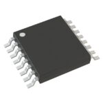 PCA9670PW,118
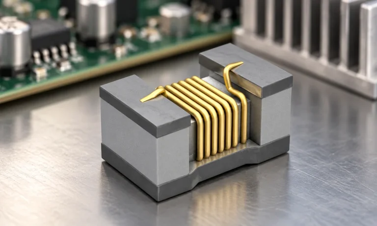
See when an inductor behaves linearly, how DC bias and saturation reduce inductance, and which current and temperature curves to check.
Read More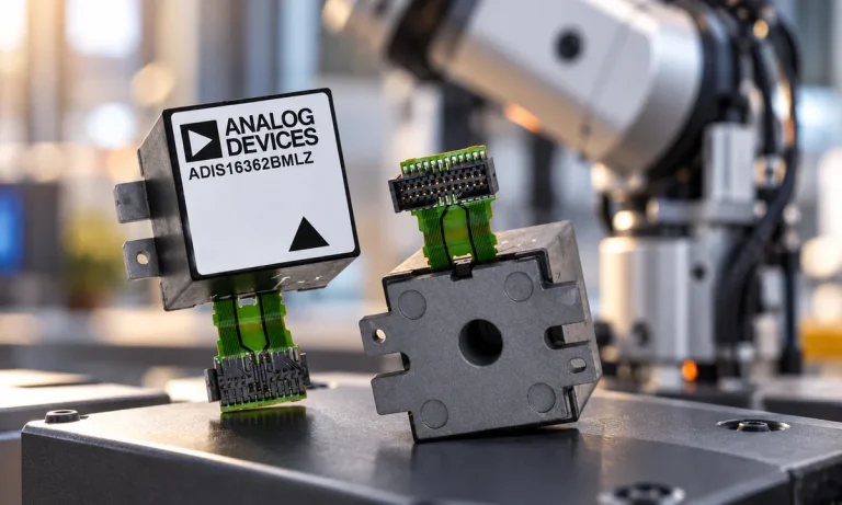
Learn what an IMU measures, how accelerometers and gyroscopes work together, why orientation estimates drift, and what to compare.
Read More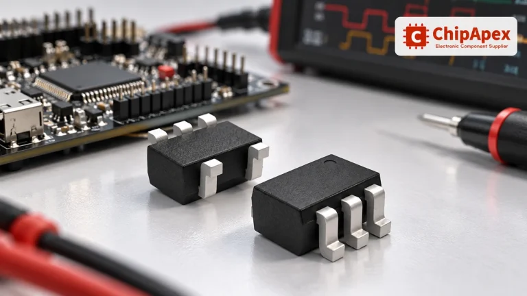
Choose logic inverter ICs by thresholds, supply, output drive and delay. Compare standard and Schmitt-trigger inputs, power sequencing and replacement checks.
Read More
PCA9670PW,118 is listed in the I/o Expanders range at ChipApex. The manufacturer field lists NXP USA Inc.. Its product description is IC XPNDR 1MHZ…
Read More
PCA9670PW,118 is listed in the I/o Expanders range at ChipApex. The manufacturer field lists NXP USA Inc.. Its product description is IC XPNDR 1MHZ…
Read More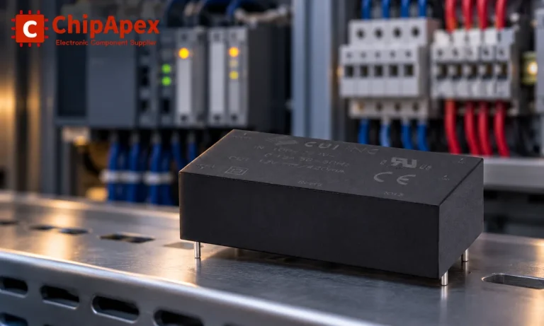
Choose an AC to DC converter by input range, output demand, isolation, efficiency and thermal derating. Compare architectures and check installation needs.
Read More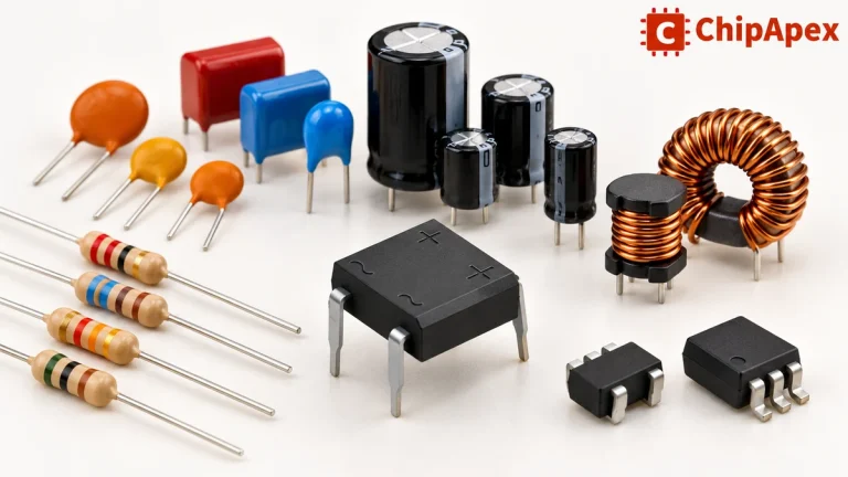
Explore electronic component types, functions, packages and datasheets. Learn selection, replacement and BOM checks before ordering parts for your PCB.
Read More
PCA9670PW,118 is listed in the I/o Expanders range at ChipApex. The manufacturer field lists NXP USA Inc.. Its product description is IC XPNDR 1MHZ…
Read More
PCA9670PW,118 is listed in the I/o Expanders range at ChipApex. The manufacturer field lists NXP USA Inc.. Its product description is IC XPNDR 1MHZ…
Read More
PCA9670PW,118 is listed in the I/o Expanders range at ChipApex. The manufacturer field lists NXP USA Inc.. Its product description is IC XPNDR 1MHZ…
Read More
PCA9670PW,118 is listed in the I/o Expanders range at ChipApex. The manufacturer field lists NXP USA Inc.. Its product description is IC XPNDR 1MHZ…
Read More
PCA9670PW,118 is listed in the I/o Expanders range at ChipApex. The manufacturer field lists NXP USA Inc.. Its product description is IC XPNDR 1MHZ…
Read More
The activity of extra discounts on wholesale prices is in full swing…
Please fill in your contact information and we will send you the latest wholesale price list.





