ChipApex | Global Electronic Components Supplier

SEARCH
Search Product
Search Post
— IC芯片 | 连接器 | 传感器 | 被动器件 —
Search productSearch post
— IC芯片 | 连接器 | 传感器 | 被动器件 —
Consult the customer manager about the wholesale price.
consultation hotline:86-132-6715-2157
email:[email protected]
Contact the product manager for consultation. One-stop consultation is available.
Do you want a lower wholesale price? Please send us your inquiry and we will reply immediately.
SN74ALVC244DWR is listed in the Buffers, Drivers, Receivers, Transceivers range at ChipApex. The manufacturer field lists Texas Instruments. Its product description is IC BUF NON-INVERT 3.6V 20SOIC. Review the specifications below when checking this part for your BOM.
The SN74ALVC244DWR is an octal buffer and line driver with 3-state outputs manufactured by Texas Instruments. It operates from a supply voltage range of 1.65 V to 3.6 V. The device is organized as two 4-bit line drivers with separate output-enable inputs. It features a maximum propagation delay of 2.8 ns at 3.3 V and provides ±24 mA output drive capability. The component supports ESD protection exceeding JESD 22 standards, including a 2000-V human-body model rating.
Verify the specific ordering suffix 'DWR' corresponds to the SOIC package and tape-and-reel carrier configuration. Confirm RoHS compliance status and lead finish specifications against current manufacturer documentation. Ensure the operating temperature range meets the application requirements before finalizing procurement orders.
Select this component for designs requiring octal buffering within the 1.65 V to 3.6 V logic family. Consider the 2.8 ns maximum propagation delay for timing-critical paths. Evaluate the ±24 mA drive strength against load requirements. Verify pin compatibility if replacing legacy devices in existing layouts.
This part belongs to the ALVC (Advanced Low-Voltage CMOS) logic family from Texas Instruments. It serves as a standard octal buffer solution for modern low-power digital interfaces. The device complements other members of the 74xx series designed for mixed-mode signal operations.
SN74ALVC244DW
The device has two separate output-enable (OE) inputs. When OE is low, data passes from A inputs to Y outputs. When OE is high, the outputs enter a high-impedance state.
To ensure the high-impedance state during power-up or power-down, the OE input should be tied to VCC through a pullup resistor.
Explore related parts through Logic, Integrated Circuits (ICs), all product categories, ChipApex homepage.
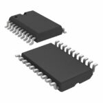 SN74ALVC244DWR
See how a MEMS gyroscope measures angular rate, why its angle estimate drifts, and which range, noise, interface and temperature specs to compare.
Read More
SN74ALVC244DWR is listed in the Buffers, Drivers, Receivers, Transceivers range at ChipApex. The manufacturer field lists Texas Instruments. Its product description is IC BUF…
Read More
SN74ALVC244DWR is listed in the Buffers, Drivers, Receivers, Transceivers range at ChipApex. The manufacturer field lists Texas Instruments. Its product description is IC BUF…
Read More
Select MOV varistors by continuous voltage, clamping behavior, surge waveform and repetition. Check thermal disconnection, fuse coordination and replacements.
Read More
Choose an AC to DC converter by input range, output demand, isolation, efficiency and thermal derating. Compare architectures and check installation needs.
Read More
SN74ALVC244DWR is listed in the Buffers, Drivers, Receivers, Transceivers range at ChipApex. The manufacturer field lists Texas Instruments. Its product description is IC BUF…
Read More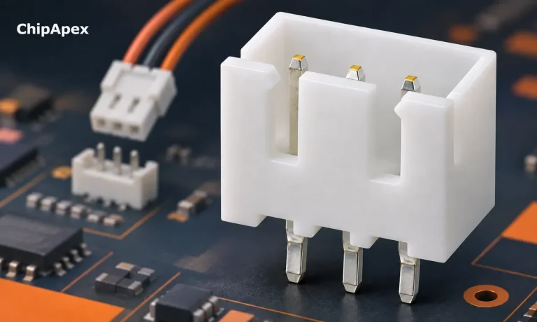
Choose a pin header by pitch, mating geometry, current rating and mounting. Learn why matching pin count and spacing does not guarantee compatibility.
Read More
SN74ALVC244DWR is listed in the Buffers, Drivers, Receivers, Transceivers range at ChipApex. The manufacturer field lists Texas Instruments. Its product description is IC BUF…
Read More
Learn what an integrated circuit is, how ICs work, the main types and the specs to check before choosing a part for your design…
Read More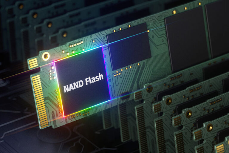
SN74ALVC244DWR is listed in the Buffers, Drivers, Receivers, Transceivers range at ChipApex. The manufacturer field lists Texas Instruments. Its product description is IC BUF…
Read More
SN74ALVC244DWR is listed in the Buffers, Drivers, Receivers, Transceivers range at ChipApex. The manufacturer field lists Texas Instruments. Its product description is IC BUF…
Read More
SN74ALVC244DWR is listed in the Buffers, Drivers, Receivers, Transceivers range at ChipApex. The manufacturer field lists Texas Instruments. Its product description is IC BUF…
Read More
The activity of extra discounts on wholesale prices is in full swing…
Please fill in your contact information and we will send you the latest wholesale price list.