 ChipApex | Global Electronic Components Supplier

SEARCH
Search Product
Search Post
— IC芯片 | 连接器 | 传感器 | 被动器件 —
Search productSearch post
— IC芯片 | 连接器 | 传感器 | 被动器件 —
Consult the customer manager about the wholesale price.
consultation hotline:86-132-6715-2157
email:[email protected]
Contact the product manager for consultation. One-stop consultation is available.
Do you want a lower wholesale price? Please send us your inquiry and we will reply immediately.
SN74HC368PWR is listed in the Buffers, Drivers, Receivers, Transceivers range at ChipApex. The manufacturer field lists Texas Instruments. Its product description is IC BUFFER INVERT 6V 16TSSOP. Review the specifications below when checking this part for your BOM.
The SN74HC368PWR is a hex inverting buffer and line driver with 3-state outputs manufactured by Texas Instruments. It operates within a supply voltage range of 2 V to 6 V and supports an operating temperature from -40°C to +85°C. The device features low power consumption with a maximum ICC of 80 µA and typical propagation delay of 10 ns. It provides high-current 3-state outputs capable of driving bus lines, memory address registers, or up to 15 LSTTL loads.
Verify the specific package type and suffix against the manufacturer's current orderable addendum to ensure compatibility with design requirements. Confirm RoHS compliance status and lead finish specifications directly from the datasheet documentation before finalizing procurement decisions.
Select this component when designing systems requiring hex inverting buffers with 3-state capabilities. Ensure the application voltage falls within the 2 V to 6 V range and consider the thermal resistance characteristics of the TSSOP-16 package for proper heat dissipation during operation.
This part belongs to the SNx4HC368 family of hex inverting buffers and line drivers. It is available in multiple packages including SOIC, PDIP, SO, and TSSOP. The device is part of Texas Instruments' standard catalog logic IC lineup, offering a versatile solution for digital signal buffering and inversion tasks.
SN74HC368DR
The OE (Output Enable) inputs are active-low. When OE is low, the device passes inverted data from the A inputs to the Y outputs. When OE is high, the outputs enter a high-impedance state.
All unused inputs must be connected to either VCC or GND to prevent undefined operational states caused by floating voltages.
Explore related parts through Logic, Integrated Circuits (ICs), all product categories, ChipApex homepage.
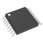 SN74HC368PWR
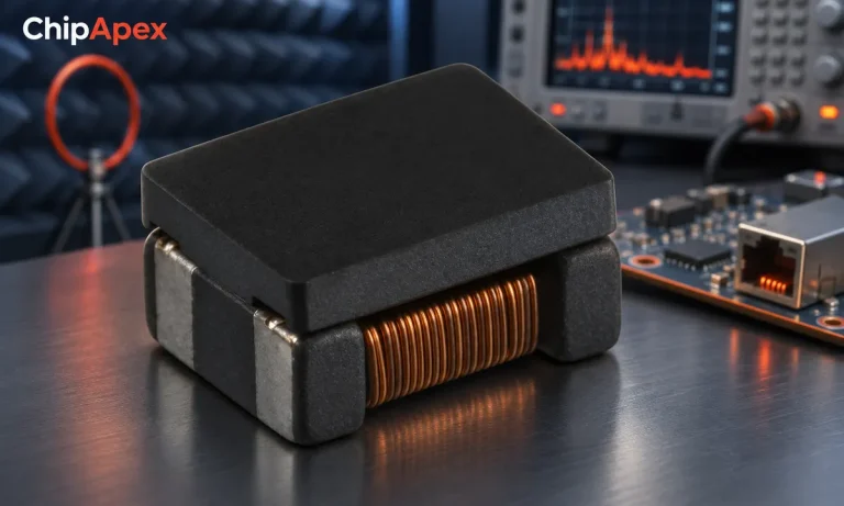
Select a common mode choke using noise frequency, current, insulation and signal integrity. Understand impedance curves, layout and filter limitations.
Read More
SN74HC368PWR is listed in the Buffers, Drivers, Receivers, Transceivers range at ChipApex. The manufacturer field lists Texas Instruments. Its product description is IC BUFFER…
Read More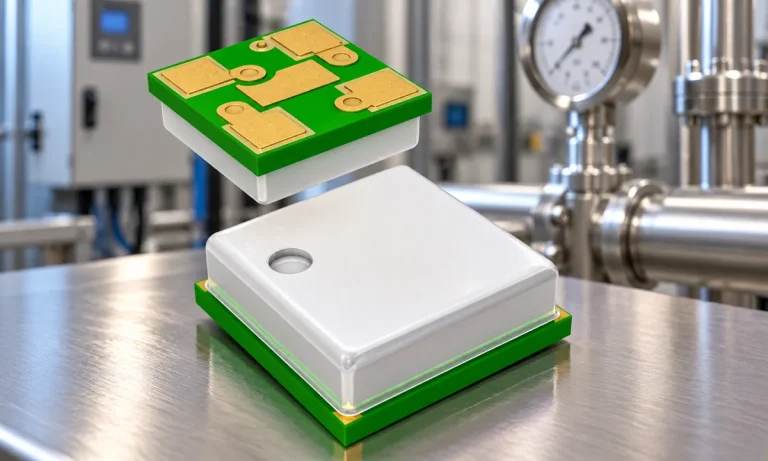
Learn how a pressure transducer converts pressure into voltage, current, or digital output, and compare pressure references and key selection specs.
Read More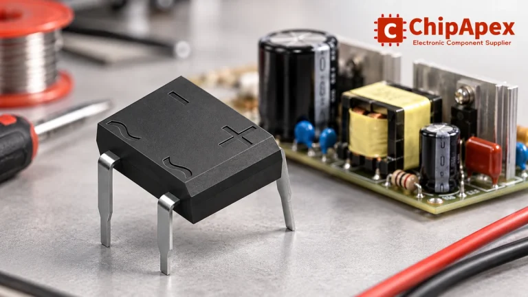
Select a bridge rectifier by reverse voltage, capacitor charging current, startup surge and cooling. Work through a stated DC voltage and ripple example.
Read More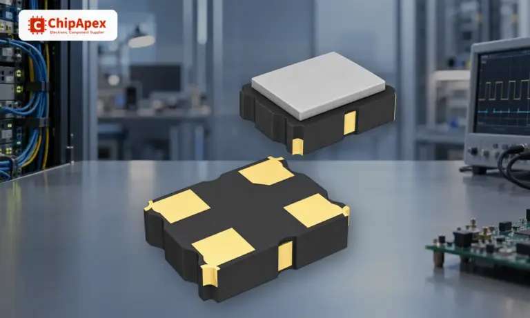
Understand how oscillators generate timing signals, how they differ from crystals, and which frequency, output and stability specs matter when choosing one.
Read More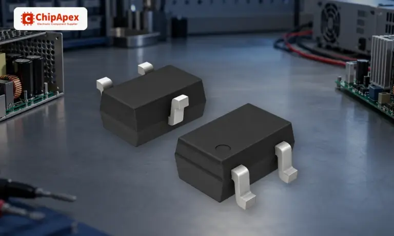
Learn how a diode conducts, how to identify anode and cathode, and when to choose rectifier, TVS, Zener or photodiode types for a circuit.
Read More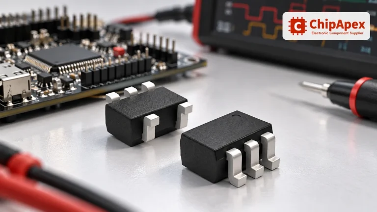
Choose logic inverter ICs by thresholds, supply, output drive and delay. Compare standard and Schmitt-trigger inputs, power sequencing and replacement checks.
Read More
SN74HC368PWR is listed in the Buffers, Drivers, Receivers, Transceivers range at ChipApex. The manufacturer field lists Texas Instruments. Its product description is IC BUFFER…
Read More
SN74HC368PWR is listed in the Buffers, Drivers, Receivers, Transceivers range at ChipApex. The manufacturer field lists Texas Instruments. Its product description is IC BUFFER…
Read More
SN74HC368PWR is listed in the Buffers, Drivers, Receivers, Transceivers range at ChipApex. The manufacturer field lists Texas Instruments. Its product description is IC BUFFER…
Read More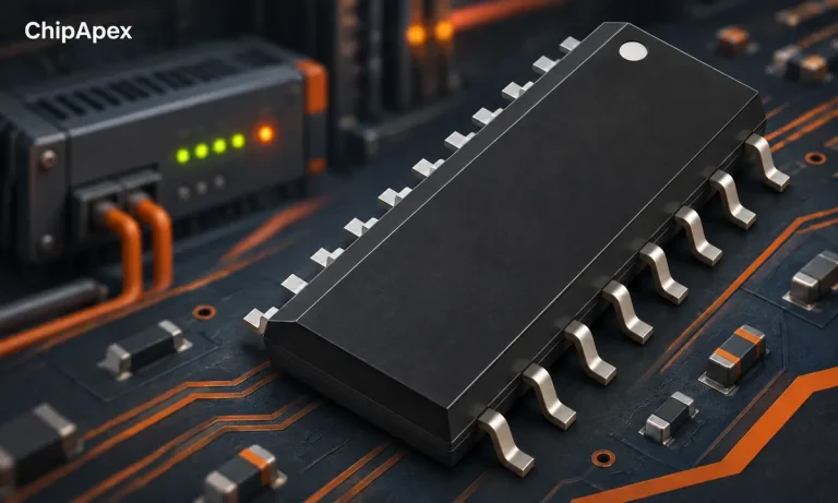
Learn what a shift register does, how bits move and when to use SIPO or PISO devices. Review latch timing, logic levels, output drive…
Read More
SN74HC368PWR is listed in the Buffers, Drivers, Receivers, Transceivers range at ChipApex. The manufacturer field lists Texas Instruments. Its product description is IC BUFFER…
Read More
The activity of extra discounts on wholesale prices is in full swing…
Please fill in your contact information and we will send you the latest wholesale price list.





