 ChipApex | Global Electronic Components Supplier

SEARCH
Search Product
Search Post
— IC芯片 | 连接器 | 传感器 | 被动器件 —
Search productSearch post
— IC芯片 | 连接器 | 传感器 | 被动器件 —
Consult the customer manager about the wholesale price.
consultation hotline:86-132-6715-2157
email:[email protected]
Contact the product manager for consultation. One-stop consultation is available.
Do you want a lower wholesale price? Please send us your inquiry and we will reply immediately.
SN74HCT540N is listed in the Buffers, Drivers, Receivers, Transceivers range at ChipApex. The manufacturer field lists Texas Instruments. Its product description is IC BUFFER INVERT 5.5V 20DIP. Review the specifications below when checking this part for your BOM.
The SN74HCT540N is an octal buffer and line driver with 3-state outputs manufactured by Texas Instruments. It operates within a supply voltage range of 4.5 V to 5.5 V and features low power consumption with a maximum ICC of 80 µA. The device provides ±6-mA output drive at 5 V and has inputs that are TTL-voltage compatible. Typical propagation delay (tpd) is 12 ns. It utilizes a data flow-through pinout arrangement where all inputs are on the opposite side from outputs, facilitating printed circuit board layout.
Verify the specific package type and temperature rating during procurement. The SN74HCT540N designation corresponds to the PDIP-20 tube package with an operating temperature range of -40°C to 85°C. Ensure compatibility with the required logic family and voltage levels before integration into the design.
Select this component when an octal buffer with inverted outputs and 3-state capability is required. It is suitable for applications needing TTL-compatible inputs and direct bus interfacing. Consider the PDIP-20 package for through-hole mounting requirements and verify that the -40°C to 85°C temperature range meets the environmental specifications of the target application.
The SN74HCT540N belongs to the HCT logic family, which combines CMOS technology with TTL-compatible input levels. It is part of the broader SN54/74HCT540 series, which includes variants in different packages such as SOIC and CDIP. This specific part number denotes the commercial grade version in a 20-pin PDIP package.
SN74HCT540DW
The 3-state control gate is a 2-input NOR. If either output-enable (OE1 or OE2) input is high, all eight outputs enter a high-impedance state.
To ensure the high-impedance state during power up or power down, OE should be tied to VCC through a pullup resistor.
Explore related parts through Logic, Integrated Circuits (ICs), all product categories, ChipApex homepage.
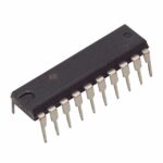 SN74HCT540N

SN74HCT540N is listed in the Buffers, Drivers, Receivers, Transceivers range at ChipApex. The manufacturer field lists Texas Instruments. Its product description is IC BUFFER…
Read More
Learn how a JFET works and how to compare bias, leakage, noise and pinout. Review practical selection questions for high-impedance analog circuits.
Read More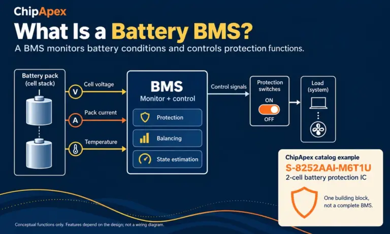
Learn what a battery BMS does, how protection differs from charging, and which pack specifications to check when sourcing BMS components through ChipApex.
Read More
SN74HCT540N is listed in the Buffers, Drivers, Receivers, Transceivers range at ChipApex. The manufacturer field lists Texas Instruments. Its product description is IC BUFFER…
Read More
SN74HCT540N is listed in the Buffers, Drivers, Receivers, Transceivers range at ChipApex. The manufacturer field lists Texas Instruments. Its product description is IC BUFFER…
Read More
SN74HCT540N is listed in the Buffers, Drivers, Receivers, Transceivers range at ChipApex. The manufacturer field lists Texas Instruments. Its product description is IC BUFFER…
Read More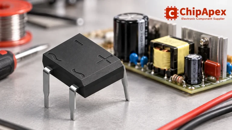
Select a bridge rectifier by reverse voltage, capacitor charging current, startup surge and cooling. Work through a stated DC voltage and ripple example.
Read More
SN74HCT540N is listed in the Buffers, Drivers, Receivers, Transceivers range at ChipApex. The manufacturer field lists Texas Instruments. Its product description is IC BUFFER…
Read More
SN74HCT540N is listed in the Buffers, Drivers, Receivers, Transceivers range at ChipApex. The manufacturer field lists Texas Instruments. Its product description is IC BUFFER…
Read More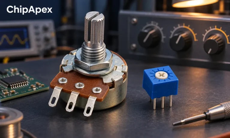
Compare rheostat and potentiometer wiring and functions. Understand divider loading, wiper current, track power and practical component selection.
Read More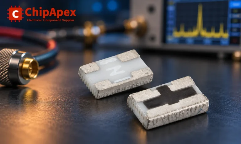
Understand RF attenuator dB values, fixed and programmable types, impedance, power limits and noise tradeoffs before choosing parts for an RF signal path.
Read More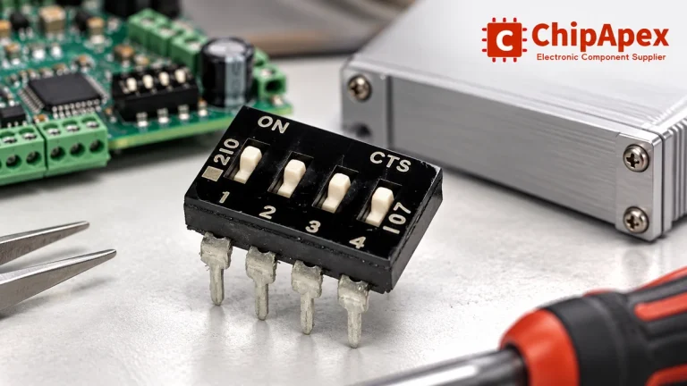
Choose a DIP switch by contact type, coded positions, footprint and signal ratings. Check logic polarity, assembly conditions and PCB configuration behavior.
Read More
The activity of extra discounts on wholesale prices is in full swing…
Please fill in your contact information and we will send you the latest wholesale price list.





