ChipApex | Global Electronic Components Supplier

SEARCH
Search Product
Search Post
— IC芯片 | 连接器 | 传感器 | 被动器件 —
Search productSearch post
— IC芯片 | 连接器 | 传感器 | 被动器件 —
Consult the customer manager about the wholesale price.
consultation hotline:86-132-6715-2157
email:[email protected]
Contact the product manager for consultation. One-stop consultation is available.
Do you want a lower wholesale price? Please send us your inquiry and we will reply immediately.
SN74LV132ADBR is listed in the Inverter Gates range at ChipApex. The manufacturer field lists Texas Instruments. Its product description is IC GATE NAND 4CH 2-INP 14SSOP. Review the specifications below when checking this part for your BOM.
The SN74LV132ADBR is a quadruple positive-NAND gate with Schmitt-trigger inputs from the Texas Instruments LV series. It operates on a supply voltage (VCC) ranging from 2 V to 5.5 V. The device features a maximum propagation delay (tpd) of 9 ns at 5 V and supports mixed-mode voltage operation on all ports. It includes Ioff support for live insertion and partial power-down modes, along with ESD protection exceeding JESD 22 standards.
Verify the specific package type matches the required PCB footprint, as the LV132A family is available in SOIC, SSOP, SOP, TSSOP, and TVSOP configurations. Confirm that the ordering suffix corresponds to the desired tape-and-reel quantity or lead finish. Ensure the selected variant meets the required operating temperature range, noting that SN74LV132A supports -40°C to 125°C.
Select this component when noise immunity is critical due to slow input ramps or noisy environments, as the Schmitt triggers filter out glitches. Choose this part for bus interface applications where minimizing output ringing is necessary. It is suitable for down-voltage translation scenarios because inputs tolerate 5.5 V even at lower supply voltages.
This device belongs to the SNx4LV132A family of quadruple positive-NAND gates with Schmitt-trigger inputs. It is manufactured by Texas Instruments using low-drive CMOS technology. The 'DB' suffix indicates the SSOP-14 package body size. It is part of the broader LV logic series designed for 2-V to 5.5-V operation.
SN74LV132ADR (SOIC-14)
The Schmitt trigger provides different input threshold levels for positive- and negative-going signals. This allows the circuit to be triggered from slow input ramps while still producing clean, jitter-free output signals.
Ioff supports live insertion, partial power-down mode, and back drive protection. It ensures that no current flows through the inputs or outputs when the device is powered off or disconnected.
Explore related parts through Logic, Integrated Circuits (ICs), all product categories, ChipApex homepage.
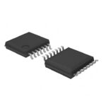 SN74LV132ADBR

SN74LV132ADBR is listed in the Inverter Gates range at ChipApex. The manufacturer field lists Texas Instruments. Its product description is IC GATE NAND 4CH…
Read More
SN74LV132ADBR is listed in the Inverter Gates range at ChipApex. The manufacturer field lists Texas Instruments. Its product description is IC GATE NAND 4CH…
Read More
Understand how an electric energy meter measures power and accumulates kWh. Review sensing, phase alignment, calibration and metering IC selection.
Read More
SN74LV132ADBR is listed in the Inverter Gates range at ChipApex. The manufacturer field lists Texas Instruments. Its product description is IC GATE NAND 4CH…
Read More
SN74LV132ADBR is listed in the Inverter Gates range at ChipApex. The manufacturer field lists Texas Instruments. Its product description is IC GATE NAND 4CH…
Read More
SN74LV132ADBR is listed in the Inverter Gates range at ChipApex. The manufacturer field lists Texas Instruments. Its product description is IC GATE NAND 4CH…
Read More
Learn the relay definition, coil and contact operation, NO and NC forms, load ratings and suppression choices. Compare mechanical, reed and solid-state types.
Read More
SN74LV132ADBR is listed in the Inverter Gates range at ChipApex. The manufacturer field lists Texas Instruments. Its product description is IC GATE NAND 4CH…
Read More
SN74LV132ADBR is listed in the Inverter Gates range at ChipApex. The manufacturer field lists Texas Instruments. Its product description is IC GATE NAND 4CH…
Read More
SN74LV132ADBR is listed in the Inverter Gates range at ChipApex. The manufacturer field lists Texas Instruments. Its product description is IC GATE NAND 4CH…
Read More
SN74LV132ADBR is listed in the Inverter Gates range at ChipApex. The manufacturer field lists Texas Instruments. Its product description is IC GATE NAND 4CH…
Read More
SN74LV132ADBR is listed in the Inverter Gates range at ChipApex. The manufacturer field lists Texas Instruments. Its product description is IC GATE NAND 4CH…
Read More
The activity of extra discounts on wholesale prices is in full swing…
Please fill in your contact information and we will send you the latest wholesale price list.