ChipApex | Global Electronic Components Supplier

SEARCH
Search Product
Search Post
— IC芯片 | 连接器 | 传感器 | 被动器件 —
Search productSearch post
— IC芯片 | 连接器 | 传感器 | 被动器件 —
Consult the customer manager about the wholesale price.
consultation hotline:86-132-6715-2157
email:[email protected]
Contact the product manager for consultation. One-stop consultation is available.
Do you want a lower wholesale price? Please send us your inquiry and we will reply immediately.
SN74LVC3G14DCUT is listed in the Inverter Gates range at ChipApex. The manufacturer field lists Texas Instruments. Its product description is IC INVERT SCHMITT 3CH 3IN 8VSSOP. Review the specifications below when checking this part for your BOM.
The SN74LVC3G14DCUT is a triple Schmitt-trigger inverter from the Texas Instruments SN74LVC family, housed in an 8-pin VSSOP package. It operates on a supply voltage range of 1.65V to 5.5V with a maximum static current of 10µA. The device provides high noise immunity and features output drive currents of 32mA for both high and low states. At 5V with a 50pF load, the maximum propagation delay is 4.3ns. It supports logic levels from 0.7V to 2.5V (low) and 1.4V to 3.7V (high), functioning within a temperature range of -40°C to +125°C.
Verify the specific suffix 'T' indicates tape-and-reel packaging when ordering. Confirm the voltage range and package type match design requirements. Check RoHS compliance status as per manufacturer documentation. Ensure ESD handling procedures are followed during assembly due to CMOS sensitivity.
Select this component when noise immunity is critical for signal integrity. Compare propagation delays against system timing constraints at the target supply voltage. Evaluate package size suitability for PCB layout density. Consider the wide temperature range for industrial or automotive applications.
This part belongs to the SN74LVC series, designed for low-voltage CMOS operations. It serves as a fundamental building block for digital logic inversion with hysteresis. The VSSOP-8 package offers space-efficient mounting for portable and compact electronic devices.
It provides hysteresis to prevent multiple output transitions when the input signal is near the threshold voltage, ensuring stable switching in noisy conditions.
No, both suffixes refer to the same electrical specifications; the difference lies solely in the packaging format (cut tape vs. reel).
Explore related parts through Logic, Integrated Circuits (ICs), all product categories, ChipApex homepage.
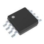 SN74LVC3G14DCUT

SN74LVC3G14DCUT is listed in the Inverter Gates range at ChipApex. The manufacturer field lists Texas Instruments. Its product description is IC INVERT SCHMITT 3CH…
Read More
SN74LVC3G14DCUT is listed in the Inverter Gates range at ChipApex. The manufacturer field lists Texas Instruments. Its product description is IC INVERT SCHMITT 3CH…
Read More
SN74LVC3G14DCUT is listed in the Inverter Gates range at ChipApex. The manufacturer field lists Texas Instruments. Its product description is IC INVERT SCHMITT 3CH…
Read More
SN74LVC3G14DCUT is listed in the Inverter Gates range at ChipApex. The manufacturer field lists Texas Instruments. Its product description is IC INVERT SCHMITT 3CH…
Read More
Understand how a comparator switches at a voltage threshold, why hysteresis prevents chatter, and which output and input specs matter.
Read More
Understand UART protocol framing, baud rate and electrical interfaces. Learn 8N1 timing, TX/RX wiring, buffering and practical troubleshooting steps.
Read More
SN74LVC3G14DCUT is listed in the Inverter Gates range at ChipApex. The manufacturer field lists Texas Instruments. Its product description is IC INVERT SCHMITT 3CH…
Read More
SN74LVC3G14DCUT is listed in the Inverter Gates range at ChipApex. The manufacturer field lists Texas Instruments. Its product description is IC INVERT SCHMITT 3CH…
Read More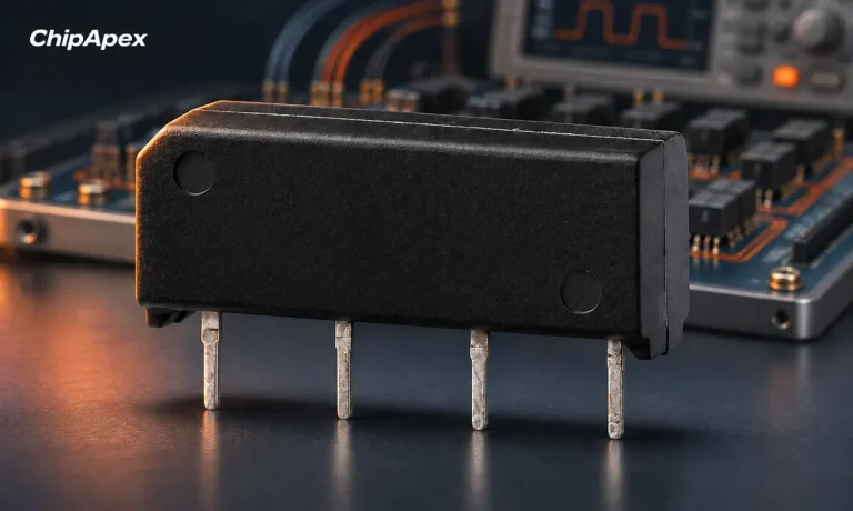
Choose a reed relay for signal switching. Understand hot and cold switching, leakage, contact resistance, isolation and measurement settling requirements.
Read More
SN74LVC3G14DCUT is listed in the Inverter Gates range at ChipApex. The manufacturer field lists Texas Instruments. Its product description is IC INVERT SCHMITT 3CH…
Read More
Understand load cell sensor output, bridge wiring and calibration. Learn how mV/V sensitivity, mechanics and ADC noise affect measurement accuracy.
Read More
SN74LVC3G14DCUT is listed in the Inverter Gates range at ChipApex. The manufacturer field lists Texas Instruments. Its product description is IC INVERT SCHMITT 3CH…
Read More
The activity of extra discounts on wholesale prices is in full swing…
Please fill in your contact information and we will send you the latest wholesale price list.