 ChipApex | Global Electronic Components Supplier

SEARCH
Search Product
Search Post
— IC芯片 | 连接器 | 传感器 | 被动器件 —
Search productSearch post
— IC芯片 | 连接器 | 传感器 | 被动器件 —
Consult the customer manager about the wholesale price.
consultation hotline:86-132-6715-2157
email:[email protected]
Contact the product manager for consultation. One-stop consultation is available.
Do you want a lower wholesale price? Please send us your inquiry and we will reply immediately.
ADADC71JD is listed in the Analog To Digital Converters (ADC) range at ChipApex. The manufacturer field lists Analog Devices Inc.. Its product description is IC ADC 16BIT SAR 32BBDIP. Review the specifications below when checking this part for your BOM.
The ADADC71JD is a 16-bit hybrid analog-to-digital converter featuring an internal reference and clock. It offers ±0.006% maximum linearity error and supports input ranges of ±2.5 V, ±5 V, ±10 V, 0 to +5 V, 0 to +10 V, and 0 to +20 V. The device operates on ±15 V analog and +5 V digital supplies with typical power consumption of 645 mW. Conversion time is 35 μs typical (50 μs max) for 14 bits. It utilizes parallel logic outputs and is housed in a 32-pin hermetic ceramic DIP package.
Verify the specific suffix JD against the ordering guide to confirm the ±0.006% linearity specification and commercial temperature range. Ensure the design accommodates the required ±15 V and +5 V supply rails. Confirm that the 32-pin ceramic DIP footprint matches the PCB layout constraints. Check for ESD sensitivity precautions during handling.
Select the ADADC71KD if a tighter linearity specification of ±0.003% is required. Consider the short cycle capability if lower resolution with faster throughput is sufficient for the application. Evaluate the need for external gain and offset adjustment circuits to minimize drift errors over the operating temperature range.
The ADADC71 is part of Analog Devices' high-precision hybrid ADC family. It combines a 16-bit successive-approximation register with a monolithic DAC. The JD variant specifies a maximum linearity error of ±0.006% FSR. It is designed for applications requiring high stability and accuracy without external precision components.
Public confirmed substitute part numbers are not available in the provided documentation. The serial output function was discontinued after date code 0120; verify date codes if legacy compatibility is required.
It uses complementary straight binary (CSB) for unipolar input ranges and complementary offset binary (COB) for bipolar ranges. Complementary two's complement (CTC) can be obtained by inverting Pin 1 (MSB).
The maximum conversion time is 50 μs for 14 bits. Short cycle capability allows termination after any number of bits, reducing time for lower resolutions (e.g., 35.6 μs for 10 bits).
Initial gain and offset errors are specified at ±0.2% and ±0.1% FSR respectively. External trim circuits using potentiometers can adjust these errors to zero for higher precision.
Explore related parts through Data Acquisition, Integrated Circuits (ICs), all product categories, ChipApex homepage.
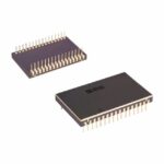 ADADC71JD

ADADC71JD is listed in the Analog To Digital Converters (ADC) range at ChipApex. The manufacturer field lists Analog Devices Inc.. Its product description is…
Read More
Understand thermal fuse operation, Tf, Th and Tm, electrical ratings and mounting. Check temperature limits and replacement requirements for your design.
Read More
Choose an AC to DC converter by input range, output demand, isolation, efficiency and thermal derating. Compare architectures and check installation needs.
Read More
ADADC71JD is listed in the Analog To Digital Converters (ADC) range at ChipApex. The manufacturer field lists Analog Devices Inc.. Its product description is…
Read More
ADADC71JD is listed in the Analog To Digital Converters (ADC) range at ChipApex. The manufacturer field lists Analog Devices Inc.. Its product description is…
Read More
ADADC71JD is listed in the Analog To Digital Converters (ADC) range at ChipApex. The manufacturer field lists Analog Devices Inc.. Its product description is…
Read More
ADADC71JD is listed in the Analog To Digital Converters (ADC) range at ChipApex. The manufacturer field lists Analog Devices Inc.. Its product description is…
Read More
ADADC71JD is listed in the Analog To Digital Converters (ADC) range at ChipApex. The manufacturer field lists Analog Devices Inc.. Its product description is…
Read More
ADADC71JD is listed in the Analog To Digital Converters (ADC) range at ChipApex. The manufacturer field lists Analog Devices Inc.. Its product description is…
Read More
ADADC71JD is listed in the Analog To Digital Converters (ADC) range at ChipApex. The manufacturer field lists Analog Devices Inc.. Its product description is…
Read More
See how a MEMS gyroscope measures angular rate, why its angle estimate drifts, and which range, noise, interface and temperature specs to compare.
Read More
ADADC71JD is listed in the Analog To Digital Converters (ADC) range at ChipApex. The manufacturer field lists Analog Devices Inc.. Its product description is…
Read More
The activity of extra discounts on wholesale prices is in full swing…
Please fill in your contact information and we will send you the latest wholesale price list.





