 ChipApex | Global Electronic Components Supplier

SEARCH
Search Product
Search Post
— IC芯片 | 连接器 | 传感器 | 被动器件 —
Search productSearch post
— IC芯片 | 连接器 | 传感器 | 被动器件 —
Consult the customer manager about the wholesale price.
consultation hotline:86-132-6715-2157
email:[email protected]
Contact the product manager for consultation. One-stop consultation is available.
Do you want a lower wholesale price? Please send us your inquiry and we will reply immediately.
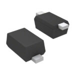
BAR6502VH6327XTSA1 is listed in the RF Diode range at ChipApex. The manufacturer field lists Infineon Technologies. Its product description is RF DIODE PIN 30V 250MW PG-SC79-2. Review the specifications below when checking this part for your BOM.
The BAR6502VH6327XTSA1 is a silicon PIN diode from the BAR65 series, designed for mobile communication low-loss transmit-receiver switches and TV-tuner band switching. It features a SC79 (SOD-523) package with single lead configuration. Key electrical parameters include a maximum reverse voltage of 30 V and a forward current rating of 100 mA. The device exhibits very low forward resistance, typically 0.65 Ω at 5 mA, and low capacitance, typically 0.5 pF at 0 V. Total power dissipation is rated at 250 mW, with a junction temperature limit of 150 °C and an operating temperature range from -55 °C to 125 °C.
Verify component authenticity by checking the marking code against Infineon's official date code tables. Confirm the package type matches the required footprint. Ensure the ordering suffix aligns with specific tape-and-reel requirements. Cross-reference the datasheet revision to confirm parameter consistency before finalizing procurement orders.
Select this component when designing circuits that require minimal insertion loss and low capacitance in the RF path. Consider the thermal resistance characteristics if operating near the upper temperature limits. Evaluate the forward voltage drop at expected bias currents to ensure adequate drive levels are met within the system constraints.
This part belongs to the BAR65 series of silicon PIN diodes manufactured by Infineon Technologies. The series includes variants like BAR65-02L and BAR65-03W, which differ primarily in package types such as TSLP-2-1 or SOD323. These components share similar electrical performance profiles tailored for RF switching and tuning applications.
Direct substitutes within the same family include BAR65-02L and BAR65-03W, though package differences must be accounted for during PCB layout adaptation. Verify pinout compatibility and thermal dissipation capabilities when transitioning between these specific series variants.
The typical diode capacitance is 0.5 pF when measured at 0 V reverse bias.
The maximum junction temperature (Tj) is specified as 150 °C.
Forward resistance decreases as forward current increases; it is typically 1 Ω at 1 mA and 0.56 Ω at 10 mA.
Explore related parts through Diodes, Discrete Semiconductor Products, all product categories, ChipApex homepage.
 BAR6502VH6327XTSA1

BAR6502VH6327XTSA1 is listed in the RF Diode range at ChipApex. The manufacturer field lists Infineon Technologies. Its product description is RF DIODE PIN 30V…
Read More
BAR6502VH6327XTSA1 is listed in the RF Diode range at ChipApex. The manufacturer field lists Infineon Technologies. Its product description is RF DIODE PIN 30V…
Read More
BAR6502VH6327XTSA1 is listed in the RF Diode range at ChipApex. The manufacturer field lists Infineon Technologies. Its product description is RF DIODE PIN 30V…
Read More
BAR6502VH6327XTSA1 is listed in the RF Diode range at ChipApex. The manufacturer field lists Infineon Technologies. Its product description is RF DIODE PIN 30V…
Read More
BAR6502VH6327XTSA1 is listed in the RF Diode range at ChipApex. The manufacturer field lists Infineon Technologies. Its product description is RF DIODE PIN 30V…
Read More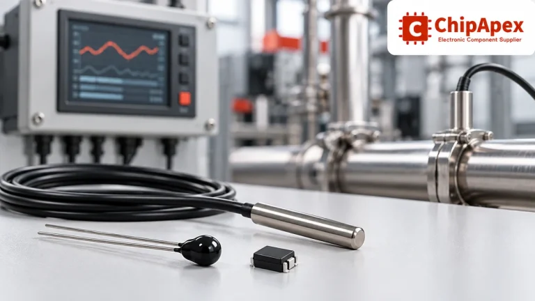
Compare thermistors, RTDs, thermocouples and temperature ICs. Learn how range, accuracy, response, interfaces and mounting affect component selection.
Read More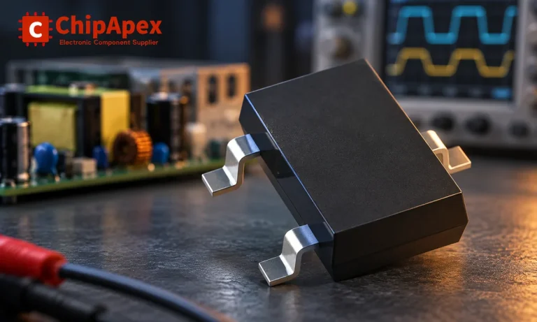
Learn how rectifiers convert AC to DC, compare half-wave and bridge circuits, and select voltage, current, recovery and thermal ratings for your design.
Read More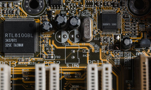
BAR6502VH6327XTSA1 is listed in the RF Diode range at ChipApex. The manufacturer field lists Infineon Technologies. Its product description is RF DIODE PIN 30V…
Read More
BAR6502VH6327XTSA1 is listed in the RF Diode range at ChipApex. The manufacturer field lists Infineon Technologies. Its product description is RF DIODE PIN 30V…
Read More
BAR6502VH6327XTSA1 is listed in the RF Diode range at ChipApex. The manufacturer field lists Infineon Technologies. Its product description is RF DIODE PIN 30V…
Read More
BAR6502VH6327XTSA1 is listed in the RF Diode range at ChipApex. The manufacturer field lists Infineon Technologies. Its product description is RF DIODE PIN 30V…
Read More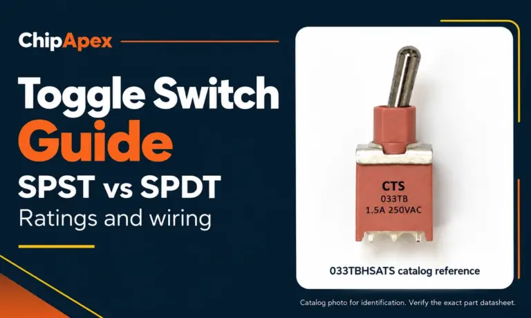
Compare SPST and SPDT toggle switches, understand AC/DC ratings, and follow wiring examples. Check contact action, mounting and parts in the ChipApex catalog.
Read More
The activity of extra discounts on wholesale prices is in full swing…
Please fill in your contact information and we will send you the latest wholesale price list.




