 ChipApex | Global Electronic Components Supplier
DG613DJ
Search Product
Search Post
— IC芯片 | 连接器 | 传感器 | 被动器件 —
Search productSearch post
— IC芯片 | 连接器 | 传感器 | 被动器件 —
Consult the customer manager about the wholesale price.
consultation hotline:86-132-6715-2157
email:[email protected]
Contact the product manager for consultation. One-stop consultation is available.
Do you want a lower wholesale price? Please send us your inquiry and we will reply immediately.
The DG613DJ is a high-speed, low-glitch analog switch manufactured by Vishay Siliconix. It features four independently controlled single-pole single-throw (SPST) switches within a 16-pin plastic dual-in-line package. The device utilizes a proprietary D/CMOS process combining lateral DMOS switching FETs with CMOS control logic to achieve fast switching speeds and minimal charge injection. It supports both single and dual power supplies, operating within a voltage range of -10 V to +21 V for the analog supply and up to +21 V for the logic supply. Key electrical parameters include a maximum on-resistance of 45 Ω at room temperature, a bandwidth of 500 MHz, and turn-on/turn-off times as low as 12 ns and 8 ns respectively under specific test conditions.
Verify the component status before integration, as availability may vary across distributors. Confirm the specific suffix 'DJ' corresponds to the 16-pin plastic DIP package and the -40 °C to +85 °C operating temperature range required for your design. Ensure compatibility with 5 V CMOS logic levels for control inputs. Check for RoHS compliance status if environmental regulations apply to your manufacturing process.
Select the DG613DJ when a mix of normally open and normally closed switches is required within a single package, unlike the DG611 or DG612 which offer uniform switch states. Consider this part for applications demanding high speed (12 ns turn-on) and low charge injection (±2 pC). Verify that the 16-pin DIP package fits your PCB layout constraints compared to SOIC or LCC alternatives. Ensure the analog signal range stays within the specified limits relative to the chosen supply voltages.
The DG613DJ belongs to the DG61x family of high-speed analog switches from Vishay Siliconix. This family includes the DG611, DG612, and DG613, which share similar electrical characteristics but differ in logic polarity and switch configuration. The DG613 specifically offers two normally open and two normally closed channels, providing versatility for complex switching topologies such as DPDT configurations.
The DG613DY serves as the surface-mount equivalent in a narrow SOIC-16 package. For through-hole applications requiring identical functionality but different logic polarity, consider the DG611DJ (all normally open) or DG612DJ (all normally closed). Verify pinout compatibility and thermal derating requirements when substituting packages.
The DG613 contains two normally open and two normally closed switches, allowing for versatile configurations like SPDT or DPDT. In contrast, the DG611 and DG612 consist of four switches with the same state (normally open or normally closed, respectively), differing only in their logic input polarity.
Signals on the source (S) or drain (D) pins that exceed the positive supply (V+) or negative supply (V-) will be clamped by internal diodes. Designers must limit the forward diode current to the maximum current ratings to prevent damage.
The DG613 features low charge injection, typically ±2 pC, which helps minimize switching transients and offset errors in sensitive applications like sample-and-hold circuits.
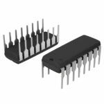 DG613DJ
The activity of extra discounts on wholesale prices is in full swing…
Please fill in your contact information and we will send you the latest wholesale price list.





