 ChipApex | Global Electronic Components Supplier
MCR8DCMT4
Search Product
Search Post
— IC芯片 | 连接器 | 传感器 | 被动器件 —
Search productSearch post
— IC芯片 | 连接器 | 传感器 | 被动器件 —
Consult the customer manager about the wholesale price.
consultation hotline:86-132-6715-2157
email:[email protected]
Contact the product manager for consultation. One-stop consultation is available.
Do you want a lower wholesale price? Please send us your inquiry and we will reply immediately.
The MCR8DCMT4 is a Silicon Controlled Rectifier (SCR) manufactured by onsemi, designed for high-volume industrial and consumer applications. It features a reverse-blocking thyristor structure housed in a surface-mount DPAK package (Case 369C). The device supports an RMS on-state current of 8.0 A and offers peak repetitive off-state voltage ratings of 600 V or 800 V depending on the specific suffix variant. Key electrical characteristics include a peak on-state voltage of 1.8 V maximum and a gate trigger current of up to 15 mA at 25°C. The component operates within a junction temperature range of -40°C to 125°C.
Verify the specific voltage rating suffix (M for 600V or N for 800V) required for your circuit design before ordering. Confirm whether the Pb-free package designation (G suffix) is necessary for compliance with environmental regulations in your target market. Ensure the tape and reel packaging specifications align with your automated pick-and-place equipment capabilities. Cross-reference the Case 369C dimensions with your PCB footprint library to guarantee mechanical fit.
Select this component based on the required RMS current handling capability of 8.0 A and the specific blocking voltage needs of the application. Consider the thermal resistance values when designing heat dissipation strategies, as the junction-to-ambient resistance varies significantly between mounted and unmounted states. Evaluate the gate trigger requirements against your driving circuit's output capabilities to ensure reliable turn-on. Assess the operating temperature range to confirm suitability for the intended environmental conditions.
This SCR belongs to the MCR8DC series from onsemi, which includes variants with different voltage ratings. The series is engineered for cost-effective solutions in mass-produced electronics. The DPAK package provides a balance between power handling and space efficiency compared to through-hole alternatives. This family of devices is widely utilized in general-purpose switching applications where robust thyristor performance is required.
Direct replacements must match the 8A RMS current rating and the specific 600V or 800V blocking voltage. Verify that substitute components offer compatible gate trigger characteristics and utilize the same or equivalent surface-mount package dimensions to maintain PCB compatibility.
The primary difference lies in the peak repetitive off-state voltage rating. The MCR8DCM variant is rated for 600 V, while the MCR8DCN variant is rated for 800 V. All other electrical characteristics and physical dimensions remain identical.
The gate trigger current typically decreases as the junction temperature increases. Data sheets indicate that the typical gate trigger current is lower at higher temperatures, such as 125°C, compared to room temperature (25°C), facilitating easier triggering in warmer environments.
The maximum lead temperature for soldering purposes is 260°C. This measurement is taken at a distance of 1/8 inch from the case body for a duration of 10 seconds.
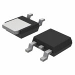 MCR8DCMT4
The activity of extra discounts on wholesale prices is in full swing…
Please fill in your contact information and we will send you the latest wholesale price list.




