 ChipApex | Global Electronic Components Supplier

SEARCH
Search Product
Search Post
— IC芯片 | 连接器 | 传感器 | 被动器件 —
Search productSearch post
— IC芯片 | 连接器 | 传感器 | 被动器件 —
Consult the customer manager about the wholesale price.
consultation hotline:86-132-6715-2157
email:[email protected]
Contact the product manager for consultation. One-stop consultation is available.
Do you want a lower wholesale price? Please send us your inquiry and we will reply immediately.
SN74HC368NE4 is listed in the Buffers, Drivers, Receivers, Transceivers range at ChipApex. The manufacturer field lists Texas Instruments. Its product description is 6-CH, 2-V TO 6-V INVERTERS WITH. Review the specifications below when checking this part for your BOM.
The SN74HC368NE4 is a hex inverting buffer and line driver with 3-state outputs manufactured by Texas Instruments. It operates within a supply voltage range of 2 V to 6 V and supports an operating temperature from -40°C to +85°C. The device features dual output-enable inputs (1OE and 2OE) that are active-low, allowing data inversion from A inputs to Y outputs when enabled. Electrical characteristics include a maximum input current of 1 µA and a typical propagation delay of 10 ns at 4.5 V. Output drive capability reaches ±6 mA at 5 V.
Verify the specific package type and lead finish against the orderable addendum in the datasheet. Confirm RoHS compliance status and moisture sensitivity level ratings prior to procurement. Ensure the ordering suffix matches the required carrier format and production status. Cross-reference thermal resistance values for the specific package variant during design validation.
Select this component for designs requiring inverted signal buffering with tri-state control capabilities. The HC series offers wide voltage compatibility suitable for various digital logic families. Consider the PDIP-16 package constraints regarding board space and thermal dissipation. Verify input transition rise/fall time requirements against the specified limits for the target supply voltage.
This part belongs to the SNx4HC368 family of hex inverting buffers and line drivers. It shares functional similarities with other HC series logic devices but is specifically optimized for memory address and clock driver applications. The NE4 suffix indicates a lead-free version of the standard SN74HC368N PDIP-16 package.
SN74HC368N
The device has two active-low output-enable inputs (1OE and 2OE). When either enable input is high, the corresponding outputs enter a high-impedance state.
A 0.1-µF capacitor is recommended for each VCC terminal to prevent power disturbances. It should be installed as close to the power terminal as possible.
Explore related parts through Logic, Integrated Circuits (ICs), all product categories, ChipApex homepage.
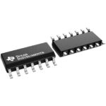 SN74HC368NE4
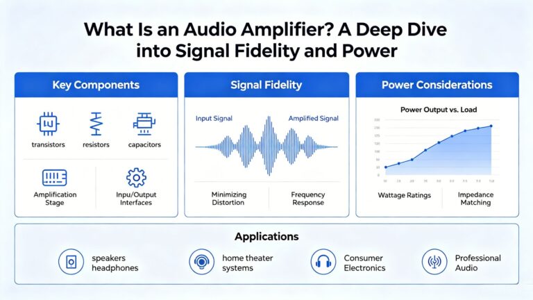
SN74HC368NE4 is listed in the Buffers, Drivers, Receivers, Transceivers range at ChipApex. The manufacturer field lists Texas Instruments. Its product description is 6-CH, 2-V…
Read More
SN74HC368NE4 is listed in the Buffers, Drivers, Receivers, Transceivers range at ChipApex. The manufacturer field lists Texas Instruments. Its product description is 6-CH, 2-V…
Read More
SN74HC368NE4 is listed in the Buffers, Drivers, Receivers, Transceivers range at ChipApex. The manufacturer field lists Texas Instruments. Its product description is 6-CH, 2-V…
Read More
SN74HC368NE4 is listed in the Buffers, Drivers, Receivers, Transceivers range at ChipApex. The manufacturer field lists Texas Instruments. Its product description is 6-CH, 2-V…
Read More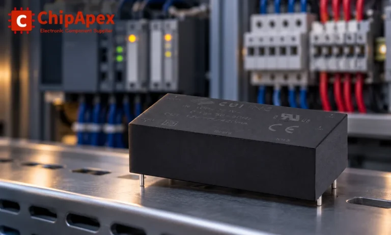
Choose an AC to DC converter by input range, output demand, isolation, efficiency and thermal derating. Compare architectures and check installation needs.
Read More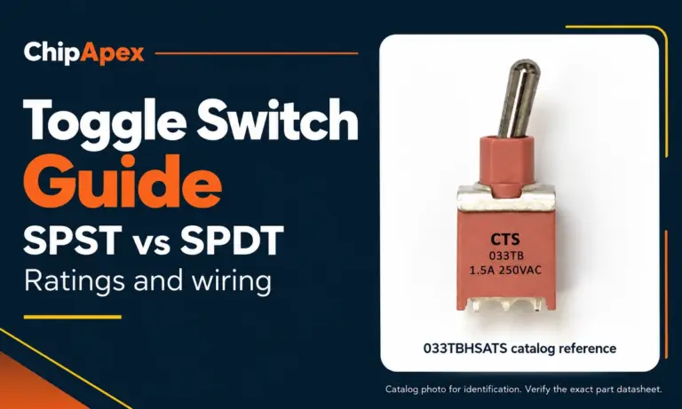
Compare SPST and SPDT toggle switches, understand AC/DC ratings, and follow wiring examples. Check contact action, mounting and parts in the ChipApex catalog.
Read More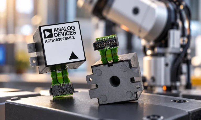
Learn what an IMU measures, how accelerometers and gyroscopes work together, why orientation estimates drift, and what to compare.
Read More
SN74HC368NE4 is listed in the Buffers, Drivers, Receivers, Transceivers range at ChipApex. The manufacturer field lists Texas Instruments. Its product description is 6-CH, 2-V…
Read More
SN74HC368NE4 is listed in the Buffers, Drivers, Receivers, Transceivers range at ChipApex. The manufacturer field lists Texas Instruments. Its product description is 6-CH, 2-V…
Read More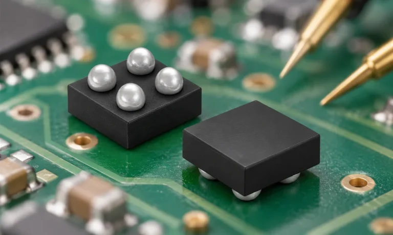
Understand how a comparator switches at a voltage threshold, why hysteresis prevents chatter, and which output and input specs matter.
Read MoreSN74HC368NE4 is listed in the Buffers, Drivers, Receivers, Transceivers range at ChipApex. The manufacturer field lists Texas Instruments. Its product description is 6-CH, 2-V…
Read More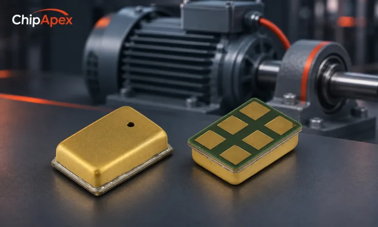
Choose a vibration sensor for machine monitoring. Compare sensing methods, bandwidth, noise and mounting, then define the signal-chain requirements.
Read More
The activity of extra discounts on wholesale prices is in full swing…
Please fill in your contact information and we will send you the latest wholesale price list.





