ChipApex | Global Electronic Components Supplier

SEARCH
Search Product
Search Post
— IC芯片 | 连接器 | 传感器 | 被动器件 —
Search productSearch post
— IC芯片 | 连接器 | 传感器 | 被动器件 —
Consult the customer manager about the wholesale price.
consultation hotline:86-132-6715-2157
email:[email protected]
Contact the product manager for consultation. One-stop consultation is available.
Do you want a lower wholesale price? Please send us your inquiry and we will reply immediately.
SN74LVC11APWR is listed in the Inverter Gates range at ChipApex. The manufacturer field lists Texas Instruments. Its product description is THREE-CHANNEL THREE-INPUT 1.2V-T. Review the specifications below when checking this part for your BOM.
The SN74LVC11APWR is a Texas Instruments logic device containing three independent 3-input AND gates. It operates within a supply voltage range of 1.1V to 3.6V and features 5.5V tolerant input pins. The component utilizes standard CMOS inputs and balanced push-pull outputs, supporting propagation delays as low as 4.1ns at 3.3V with a 50pF load. It provides latch-up performance exceeding 250mA per JESD 17 and ESD protection exceeding 2000V via the Human-Body Model.
Verify the specific package suffix 'PW' corresponds to the TSSOP-14 form factor required for your PCB layout. Confirm that the operating environment remains within the specified -40°C to +125°C temperature range. Ensure input transition rates comply with recommended limits to prevent excessive current consumption or oscillations during operation.
Select this component when a triple 3-input AND gate is required in a low-voltage 1.1V to 3.6V system. It is suitable for applications needing 5.5V input tolerance without level shifting. Consider its balanced output drive capabilities for driving light loads, but ensure capacitive loads do not exceed 50pF to maintain specified switching characteristics.
This part belongs to the SN74LVC11A family of triple 3-input AND gates manufactured by Texas Instruments. It shares functional similarities with other LVC series logic devices but is distinct in its specific 3-input configuration. The 'PWR' designation indicates the TSSOP-14 package variant available from distributors.
SN74LVC11ADWR
Unused inputs must not be left floating. They should be terminated to either VCC or ground using a pull-up or pull-down resistor, typically 10kΩ, to prevent undefined operational states.
The device can drive a load with a total capacitance less than or equal to 50pF while meeting all data sheet specifications. Exceeding this value may require adding a series resistor to limit output current.
Explore related parts through Logic, Integrated Circuits (ICs), all product categories, ChipApex homepage.
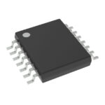 SN74LVC11APWR
SN74LVC11APWR is listed in the Inverter Gates range at ChipApex. The manufacturer field lists Texas Instruments. Its product description is THREE-CHANNEL THREE-INPUT 1.2V-T. Review…
Read More
SN74LVC11APWR is listed in the Inverter Gates range at ChipApex. The manufacturer field lists Texas Instruments. Its product description is THREE-CHANNEL THREE-INPUT 1.2V-T. Review…
Read More
SN74LVC11APWR is listed in the Inverter Gates range at ChipApex. The manufacturer field lists Texas Instruments. Its product description is THREE-CHANNEL THREE-INPUT 1.2V-T. Review…
Read More
SN74LVC11APWR is listed in the Inverter Gates range at ChipApex. The manufacturer field lists Texas Instruments. Its product description is THREE-CHANNEL THREE-INPUT 1.2V-T. Review…
Read More
SN74LVC11APWR is listed in the Inverter Gates range at ChipApex. The manufacturer field lists Texas Instruments. Its product description is THREE-CHANNEL THREE-INPUT 1.2V-T. Review…
Read More
SN74LVC11APWR is listed in the Inverter Gates range at ChipApex. The manufacturer field lists Texas Instruments. Its product description is THREE-CHANNEL THREE-INPUT 1.2V-T. Review…
Read More
SN74LVC11APWR is listed in the Inverter Gates range at ChipApex. The manufacturer field lists Texas Instruments. Its product description is THREE-CHANNEL THREE-INPUT 1.2V-T. Review…
Read More
Compare gas sensor technologies, cross-sensitivity and calibration needs. Define the gas, range and environment before choosing a sensing component.
Read More
Learn how to use ferrite beads for noise filtering. Check impedance, DC bias, placement, resonance and load-step behavior before selecting a part.
Read More
SN74LVC11APWR is listed in the Inverter Gates range at ChipApex. The manufacturer field lists Texas Instruments. Its product description is THREE-CHANNEL THREE-INPUT 1.2V-T. Review…
Read More
Understand thermal fuse operation, Tf, Th and Tm, electrical ratings and mounting. Check temperature limits and replacement requirements for your design.
Read More
Understand load cell sensor output, bridge wiring and calibration. Learn how mV/V sensitivity, mechanics and ADC noise affect measurement accuracy.
Read More
The activity of extra discounts on wholesale prices is in full swing…
Please fill in your contact information and we will send you the latest wholesale price list.