 ChipApex | Global Electronic Components Supplier

SEARCH
Search Product
Search Post
— IC芯片 | 连接器 | 传感器 | 被动器件 —
Search productSearch post
— IC芯片 | 连接器 | 传感器 | 被动器件 —
Consult the customer manager about the wholesale price.
consultation hotline:86-132-6715-2157
email:[email protected]
Contact the product manager for consultation. One-stop consultation is available.
Do you want a lower wholesale price? Please send us your inquiry and we will reply immediately.
74ACT541MTCX is listed in the Buffers, Drivers, Receivers, Transceivers range at ChipApex. The manufacturer field lists onsemi. Its product description is IC BUFF NON-INVERT 5.5V 20TSSOP. Review the specifications below when checking this part for your BOM.
The MC74ACT541MTCX is an octal buffer and line driver manufactured by onsemi, belonging to the 74ACT logic family. It features non-inverting outputs with three-state capability, allowing high-impedance isolation when disabled. The device operates within a supply voltage range of 4.5 V to 5.5 V and supports an operating temperature from -40°C to +85°C. It provides strong output drive capabilities, sourcing and sinking up to 24 mA per pin. The component utilizes a flow-through architecture with inputs and outputs positioned on opposite sides of the package, facilitating efficient printed circuit board layout.
Verify the specific ordering suffix 'MTCX' corresponds to the TSSOP-20 tape and reel packaging configuration. Confirm the device marking matches the ACT541 identifier. Ensure the procurement specification aligns with the required 4.5 V to 5.5 V operating voltage range and industrial temperature limits.
Select this component when a non-inverting octal buffer with three-state control is required for microprocessor interfaces. The flow-through architecture simplifies PCB routing compared to parallel input/output layouts. Verify compatibility with TTL logic levels if interfacing with legacy systems, as the ACT series ensures direct compatibility without additional level shifting.
This part belongs to the 74ACT541 series of octal buffers and line drivers. It serves as the non-inverting counterpart to the inverting 74ACT540 model. The device shares functional similarities with the 74AC244 and 74ACTC244 families but distinguishes itself through its specific flow-through pinout design optimized for high-density board layouts.
MC74ACT541MTC
OE1 and OE2 are active-low output enable inputs. When either pin is at a low logic level, the corresponding outputs are enabled. If both are high, all outputs enter a high-impedance state.
The flow-through architecture places inputs on one side of the package and outputs on the opposite side. This arrangement allows signals to pass directly through the device, reducing trace length and simplifying routing for microprocessor port expansions.
Explore related parts through Logic, Integrated Circuits (ICs), all product categories, ChipApex homepage.
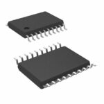 74ACT541MTCX

74ACT541MTCX is listed in the Buffers, Drivers, Receivers, Transceivers range at ChipApex. The manufacturer field lists onsemi. Its product description is IC BUFF NON-INVERT…
Read More
Compare Pt100 and Pt1000 RTDs, two-, three- and four-wire connections, excitation and self-heating. Build an error budget from element to reported temperature.
Read More
Select power transformers by input frequency, secondary VA, rectifier load, isolation, regulation and inrush. Build a clearer specification for your next RFQ.
Read More
Choose a rocker switch by AC/DC ratings, contact arrangement, illumination, panel fit and sealing. Get practical checks for engineering and component sourcing.
Read More
74ACT541MTCX is listed in the Buffers, Drivers, Receivers, Transceivers range at ChipApex. The manufacturer field lists onsemi. Its product description is IC BUFF NON-INVERT…
Read More
74ACT541MTCX is listed in the Buffers, Drivers, Receivers, Transceivers range at ChipApex. The manufacturer field lists onsemi. Its product description is IC BUFF NON-INVERT…
Read More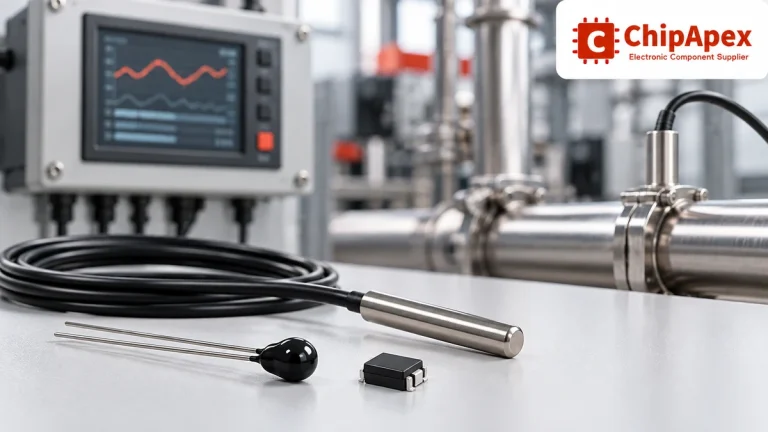
Compare thermistors, RTDs, thermocouples and temperature ICs. Learn how range, accuracy, response, interfaces and mounting affect component selection.
Read More
74ACT541MTCX is listed in the Buffers, Drivers, Receivers, Transceivers range at ChipApex. The manufacturer field lists onsemi. Its product description is IC BUFF NON-INVERT…
Read More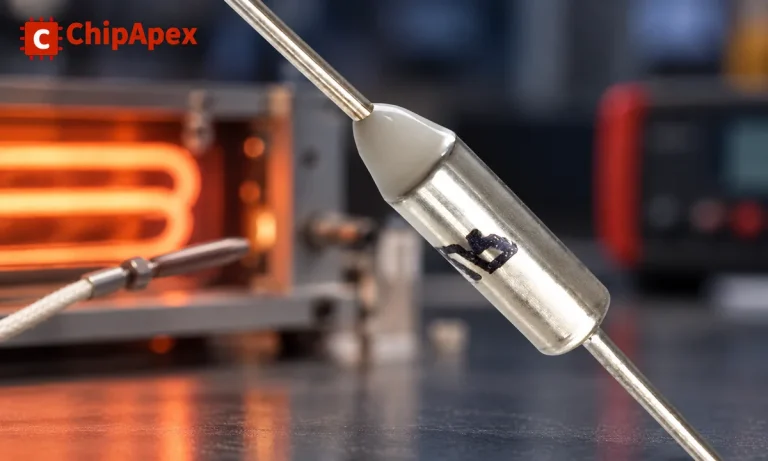
Understand thermal fuse operation, Tf, Th and Tm, electrical ratings and mounting. Check temperature limits and replacement requirements for your design.
Read More
Learn how a diode conducts, how to identify anode and cathode, and when to choose rectifier, TVS, Zener or photodiode types for a circuit.
Read More
74ACT541MTCX is listed in the Buffers, Drivers, Receivers, Transceivers range at ChipApex. The manufacturer field lists onsemi. Its product description is IC BUFF NON-INVERT…
Read More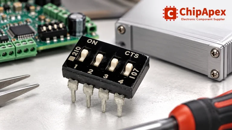
Choose a DIP switch by contact type, coded positions, footprint and signal ratings. Check logic polarity, assembly conditions and PCB configuration behavior.
Read More
The activity of extra discounts on wholesale prices is in full swing…
Please fill in your contact information and we will send you the latest wholesale price list.





