 ChipApex | Global Electronic Components Supplier

SEARCH
Search Product
Search Post
— IC芯片 | 连接器 | 传感器 | 被动器件 —
Search productSearch post
— IC芯片 | 连接器 | 传感器 | 被动器件 —
Consult the customer manager about the wholesale price.
consultation hotline:86-132-6715-2157
email:[email protected]
Contact the product manager for consultation. One-stop consultation is available.
Do you want a lower wholesale price? Please send us your inquiry and we will reply immediately.
ADAR7251WBCSZ is listed in the Analog To Digital Converters (ADC) range at ChipApex. The manufacturer field lists Analog Devices Inc.. Its product description is IC ADC 16BIT SIGMA-DELTA 48LFCSP. Review the specifications below when checking this part for your BOM.
The ADAR7251WBCSZ is a 4-channel, 16-bit simultaneous sampling analog-to-digital converter (ADC) designed for automotive LSR-FMCW and FSK-FMCW radar systems. It features an integrated low noise amplifier (LNA), programmable gain amplifier (PGA), equalizer, multibit Σ-Δ ADC, and decimation filter. The device supports sample rates from 300 kSPS to 1.8 MSPS with an input signal bandwidth up to 900 kHz at 1.2 MSPS. It operates on a single 3.3 V supply with an internal 1.8 V digital core regulator. Key specifications include a maximum gain of 45 dB in 6 dB steps, an on-chip 1.5 V reference, and flexible serial or parallel data interfaces controlled via SPI.
Verify the specific suffix WBCSZ against the manufacturer's current ordering guide to confirm package type and temperature range variations. Ensure compatibility with automotive qualification standards if required for the target application. Cross-reference the datasheet revision to confirm all electrical parameters match the design requirements before finalizing procurement.
Select this component when designing automotive radar systems requiring simultaneous sampling of four channels with high dynamic range. Consider the internal PLL and flexible clock inputs if system timing constraints require specific master clock frequencies between 16 MHz and 54 MHz. Evaluate the need for the integrated LNA and PGA to simplify the analog front-end design and reduce external component count.
The ADAR7251 belongs to Analog Devices' family of continuous-time data acquisition ADCs tailored for radar applications. It replaces traditional architectures that require separate drivers, antialiasing filters, and bipolar supplies. The device integrates the complete signal chain from analog input to digital output, simplifying PCB layout and improving system reliability in harsh automotive environments.
No public confirmed substitute part numbers are available in the provided documentation. Designers should evaluate other 4-channel 16-bit SAR or Sigma-Delta ADCs from Analog Devices or competitors, ensuring they meet the specific bandwidth, sample rate, and automotive qualification requirements of the original design.
These pins synchronize the ADC conversion process with an external ramp signal, which is essential for applications such as FSK-FMCW radar systems to ensure precise timing alignment.
Yes, the device accepts a single-ended clock input at the XIN/MCLKIN pin. An external crystal is optional; the internal oscillator can be used if a suitable clock source is provided externally within the 16 MHz to 54 MHz range.
The device eliminates the need for a high-order external antialiasing filter due to its continuous-time input architecture and integrated digital decimation filter, which provides sufficient stop-band attenuation.
Explore related parts through Data Acquisition, Integrated Circuits (ICs), all product categories, ChipApex homepage.
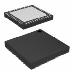 ADAR7251WBCSZ
Compare thermistors, RTDs, thermocouples and temperature ICs. Learn how range, accuracy, response, interfaces and mounting affect component selection.
Read More
Choose logic inverter ICs by thresholds, supply, output drive and delay. Compare standard and Schmitt-trigger inputs, power sequencing and replacement checks.
Read More
ADAR7251WBCSZ is listed in the Analog To Digital Converters (ADC) range at ChipApex. The manufacturer field lists Analog Devices Inc.. Its product description is…
Read More
ADAR7251WBCSZ is listed in the Analog To Digital Converters (ADC) range at ChipApex. The manufacturer field lists Analog Devices Inc.. Its product description is…
Read More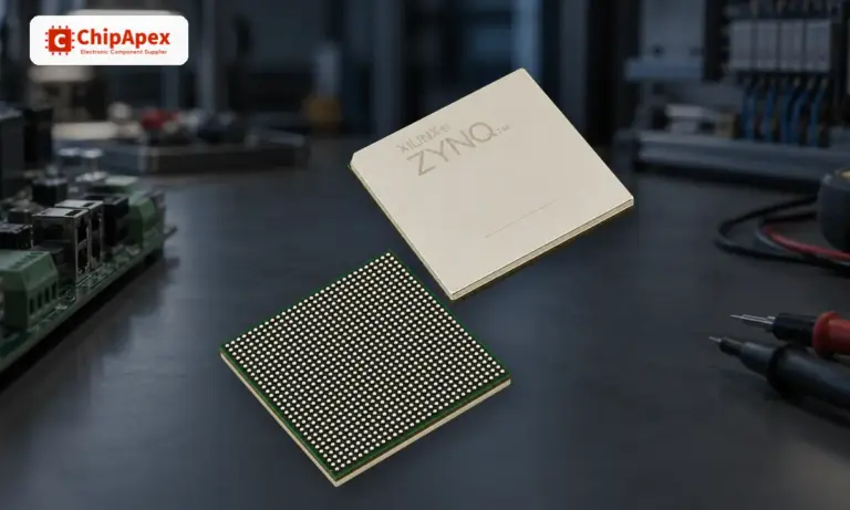
Learn what an integrated circuit is, how ICs work, the main types and the specs to check before choosing a part for your design…
Read More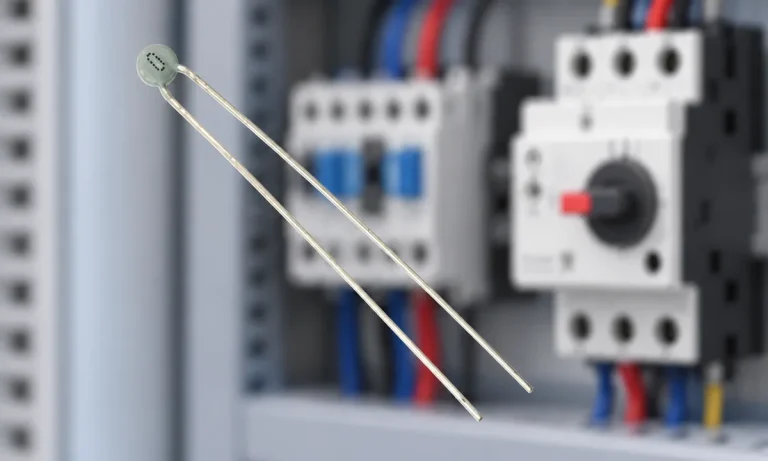
Learn why PTC resistance rises with temperature, how it differs from NTC, and which ratings matter for sensing and protection.
Read More
ADAR7251WBCSZ is listed in the Analog To Digital Converters (ADC) range at ChipApex. The manufacturer field lists Analog Devices Inc.. Its product description is…
Read More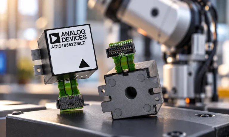
Learn what an IMU measures, how accelerometers and gyroscopes work together, why orientation estimates drift, and what to compare.
Read More
ADAR7251WBCSZ is listed in the Analog To Digital Converters (ADC) range at ChipApex. The manufacturer field lists Analog Devices Inc.. Its product description is…
Read More
ADAR7251WBCSZ is listed in the Analog To Digital Converters (ADC) range at ChipApex. The manufacturer field lists Analog Devices Inc.. Its product description is…
Read More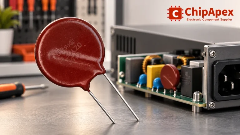
Select MOV varistors by continuous voltage, clamping behavior, surge waveform and repetition. Check thermal disconnection, fuse coordination and replacements.
Read More
ADAR7251WBCSZ is listed in the Analog To Digital Converters (ADC) range at ChipApex. The manufacturer field lists Analog Devices Inc.. Its product description is…
Read More
The activity of extra discounts on wholesale prices is in full swing…
Please fill in your contact information and we will send you the latest wholesale price list.




