ChipApex | Global Electronic Components Supplier

SEARCH
Search Product
Search Post
— IC芯片 | 连接器 | 传感器 | 被动器件 —
Search productSearch post
— IC芯片 | 连接器 | 传感器 | 被动器件 —
Consult the customer manager about the wholesale price.
consultation hotline:86-132-6715-2157
email:[email protected]
Contact the product manager for consultation. One-stop consultation is available.
Do you want a lower wholesale price? Please send us your inquiry and we will reply immediately.
CPH5512-TL-E is listed in the RF Diode range at ChipApex. The manufacturer field lists onsemi. Its product description is RF DIODE PIN 50V 5CPH. Review the specifications below when checking this part for your BOM.
The CPH5512-TL-E is a dual parallel PIN diode from onsemi, housed in a compact CPH5 (SC-74A/SOT-25) surface-mount package. It features two independent diodes within a single component to improve mounting efficiency. Key electrical specifications include a maximum reverse voltage of 50 V and a forward current rating of 50 mA. The device exhibits a typical interterminal capacitance of 0.23 pF at 50 V reverse bias and a typical forward series resistance of 5 Ω at 10 mA forward current and 100 MHz frequency. Maximum power dissipation is rated at 350 mW, with an operating junction temperature range up to +125 °C.
Verify the ordering suffix TL-E confirms the tape-and-reel shipping format containing 3,000 pieces per reel. Confirm the Pb Free designation aligns with environmental compliance requirements. Ensure the CPH5 package dimensions match the target land pattern design. Validate that the 50 V reverse voltage rating meets the peak inverse voltage demands of the specific RF application.
Select this component when a dual-diode topology is required in a minimal footprint. The low capacitance value supports operation in VHF and UHF bands where parasitic effects must be minimized. Verify that the 50 mA forward current capability satisfies the signal handling requirements. Consider the 350 mW power dissipation limit relative to the expected thermal environment during continuous operation.
This part belongs to the CPH5512 series of PIN diodes manufactured by onsemi. It utilizes the CPH5 composite package, also identified as SC-74A or SOT-25, which houses two distinct diode structures. The device is designed specifically for radio frequency applications requiring fast switching and low insertion loss characteristics.
Direct substitutes require matching the CPH5 package, 50 V reverse voltage rating, and dual parallel PIN diode configuration. Verify equivalent capacitance and series resistance values to maintain RF performance integrity in existing circuit designs.
Pins 1 and 2 are Cathodes, Pin 3 is Anode, Pin 4 is No Contact, and Pin 5 is Anode.
The typical interterminal capacitance is 0.23 pF measured at 50 V reverse voltage and 1 MHz frequency.
The maximum junction temperature is 125 °C.
Explore related parts through Diodes, Discrete Semiconductor Products, all product categories, ChipApex homepage.
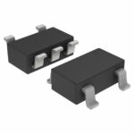 CPH5512-TL-E

CPH5512-TL-E is listed in the RF Diode range at ChipApex. The manufacturer field lists onsemi. Its product description is RF DIODE PIN 50V 5CPH.…
Read More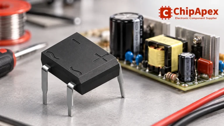
Select a bridge rectifier by reverse voltage, capacitor charging current, startup surge and cooling. Work through a stated DC voltage and ripple example.
Read More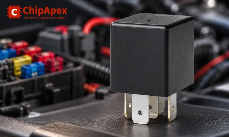
Learn the relay definition, coil and contact operation, NO and NC forms, load ratings and suppression choices. Compare mechanical, reed and solid-state types.
Read More
CPH5512-TL-E is listed in the RF Diode range at ChipApex. The manufacturer field lists onsemi. Its product description is RF DIODE PIN 50V 5CPH.…
Read More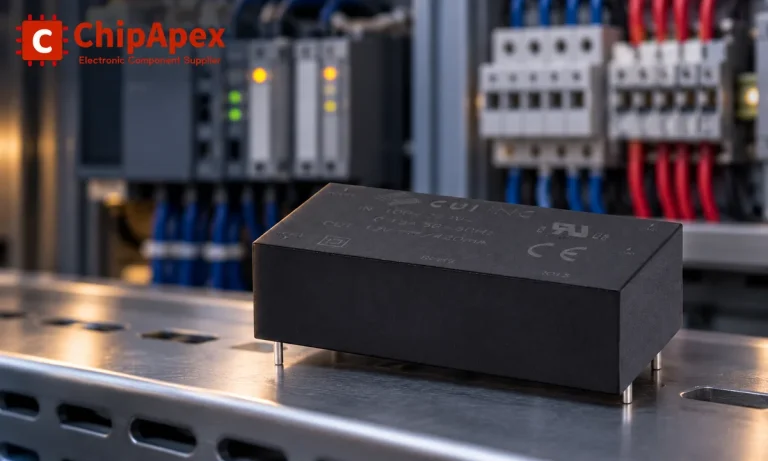
Choose an AC to DC converter by input range, output demand, isolation, efficiency and thermal derating. Compare architectures and check installation needs.
Read More
CPH5512-TL-E is listed in the RF Diode range at ChipApex. The manufacturer field lists onsemi. Its product description is RF DIODE PIN 50V 5CPH.…
Read More
CPH5512-TL-E is listed in the RF Diode range at ChipApex. The manufacturer field lists onsemi. Its product description is RF DIODE PIN 50V 5CPH.…
Read More
Learn how a diode conducts, how to identify anode and cathode, and when to choose rectifier, TVS, Zener or photodiode types for a circuit.
Read More
CPH5512-TL-E is listed in the RF Diode range at ChipApex. The manufacturer field lists onsemi. Its product description is RF DIODE PIN 50V 5CPH.…
Read More
CPH5512-TL-E is listed in the RF Diode range at ChipApex. The manufacturer field lists onsemi. Its product description is RF DIODE PIN 50V 5CPH.…
Read More
CPH5512-TL-E is listed in the RF Diode range at ChipApex. The manufacturer field lists onsemi. Its product description is RF DIODE PIN 50V 5CPH.…
Read More
CPH5512-TL-E is listed in the RF Diode range at ChipApex. The manufacturer field lists onsemi. Its product description is RF DIODE PIN 50V 5CPH.…
Read More
The activity of extra discounts on wholesale prices is in full swing…
Please fill in your contact information and we will send you the latest wholesale price list.