ChipApex | Global Electronic Components Supplier

SEARCH
Search Product
Search Post
— IC芯片 | 连接器 | 传感器 | 被动器件 —
Search productSearch post
— IC芯片 | 连接器 | 传感器 | 被动器件 —
Consult the customer manager about the wholesale price.
consultation hotline:86-132-6715-2157
email:[email protected]
Contact the product manager for consultation. One-stop consultation is available.
Do you want a lower wholesale price? Please send us your inquiry and we will reply immediately.
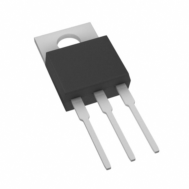
ER2006CT_T0_00001 is listed in the Diode Arrays range at ChipApex. The manufacturer field lists Panjit International Inc.. Its product description is DIODE ARRAY GP 600V 20A TO-220AB. Review the specifications below when checking this part for your BOM.
The ER2006CT_T0_00001 is a super fast recovery rectifier manufactured by Panjit International Inc. It features an epitaxial chip construction and is housed in a TO-220AB molded plastic package. The device supports a maximum recurrent peak reverse voltage of 600 V and a maximum DC blocking voltage of 600 V. It provides a maximum average forward current of 20 A at a case temperature of 90°C, with a peak forward surge current capability of 150 A. Electrical characteristics include a maximum forward voltage of 1.7 V at 10 A, a maximum reverse recovery time of 50 ns, and a typical junction capacitance of 85 pF.
Verify the specific suffix _T0_00001 against official documentation to confirm packaging details, as standard series data indicates tube packing. Ensure the component meets required thermal management standards given the 20 A rating. Confirm compliance with RoHS 2011/65/EU and IEC61249 halogen-free requirements during sourcing.
Select this component for circuits requiring high voltage isolation up to 600 V and rapid switching speeds. The TO-220AB package facilitates effective heat dissipation for continuous currents up to 20 A. Consider derating current by 20% if used with capacitive loads. Evaluate thermal resistance requirements based on ambient operating conditions.
This part belongs to the ER2000CT series of isolation superfast recovery rectifiers from Panjit International Inc. The series covers voltage ratings from 50 V to 600 V, sharing common electrical parameters such as 20 A forward current and similar recovery times. The ER2006CT specifically denotes the 600 V variant within this lineup.
Consult official datasheets for cross-referencing. Verify that any substitute matches the 600 V reverse voltage, 20 A current rating, and TO-220AB package dimensions. Ensure equivalent reverse recovery time and forward voltage characteristics are maintained.
The maximum reverse recovery time (trr) is 50 ns.
For capacitive loads, the current should be derated by 20%.
The typical junction capacitance is 85 pF, measured at 1 MHz and 4 VDC applied reverse voltage.
Explore related parts through Rectifiers, Diodes, Discrete Semiconductor Products, all product categories.
 ER2006CT_T0_00001
ER2006CT_T0_00001 is listed in the Diode Arrays range at ChipApex. The manufacturer field lists Panjit International Inc.. Its product description is DIODE ARRAY GP…
Read More
ER2006CT_T0_00001 is listed in the Diode Arrays range at ChipApex. The manufacturer field lists Panjit International Inc.. Its product description is DIODE ARRAY GP…
Read More
ER2006CT_T0_00001 is listed in the Diode Arrays range at ChipApex. The manufacturer field lists Panjit International Inc.. Its product description is DIODE ARRAY GP…
Read More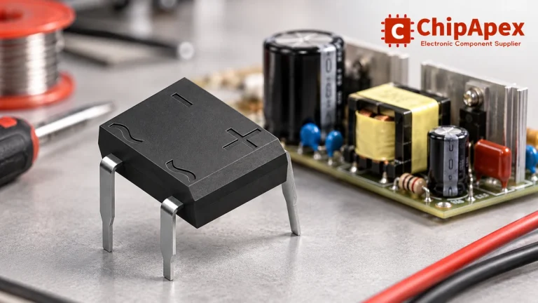
Select a bridge rectifier by reverse voltage, capacitor charging current, startup surge and cooling. Work through a stated DC voltage and ripple example.
Read More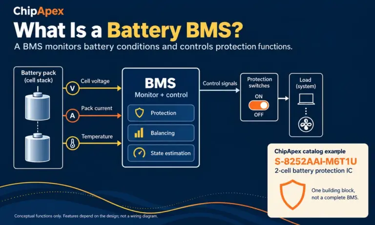
Learn what a battery BMS does, how protection differs from charging, and which pack specifications to check when sourcing BMS components through ChipApex.
Read More
ER2006CT_T0_00001 is listed in the Diode Arrays range at ChipApex. The manufacturer field lists Panjit International Inc.. Its product description is DIODE ARRAY GP…
Read More
ER2006CT_T0_00001 is listed in the Diode Arrays range at ChipApex. The manufacturer field lists Panjit International Inc.. Its product description is DIODE ARRAY GP…
Read More
Learn why PTC resistance rises with temperature, how it differs from NTC, and which ratings matter for sensing and protection.
Read More
ER2006CT_T0_00001 is listed in the Diode Arrays range at ChipApex. The manufacturer field lists Panjit International Inc.. Its product description is DIODE ARRAY GP…
Read More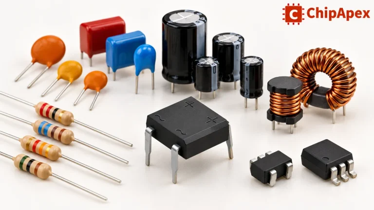
Explore electronic component types, functions, packages and datasheets. Learn selection, replacement and BOM checks before ordering parts for your PCB.
Read More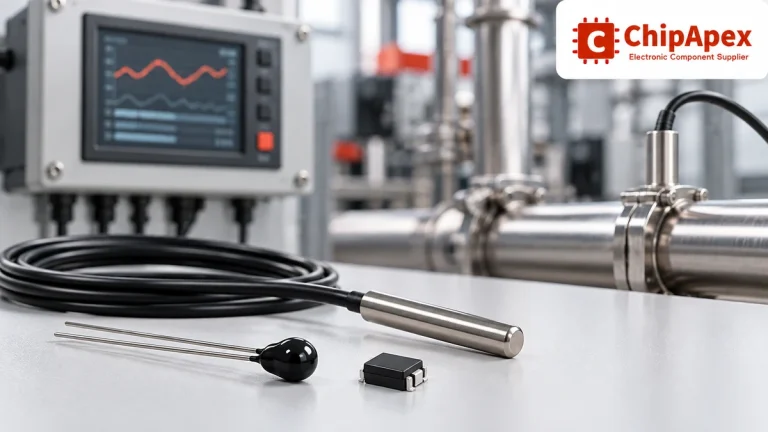
Compare thermistors, RTDs, thermocouples and temperature ICs. Learn how range, accuracy, response, interfaces and mounting affect component selection.
Read More
ER2006CT_T0_00001 is listed in the Diode Arrays range at ChipApex. The manufacturer field lists Panjit International Inc.. Its product description is DIODE ARRAY GP…
Read More
The activity of extra discounts on wholesale prices is in full swing…
Please fill in your contact information and we will send you the latest wholesale price list.