 ChipApex | Global Electronic Components Supplier

SEARCH
Search Product
Search Post
— IC芯片 | 连接器 | 传感器 | 被动器件 —
Search productSearch post
— IC芯片 | 连接器 | 传感器 | 被动器件 —
Consult the customer manager about the wholesale price.
consultation hotline:86-132-6715-2157
email:[email protected]
Contact the product manager for consultation. One-stop consultation is available.
Do you want a lower wholesale price? Please send us your inquiry and we will reply immediately.
FMW34CP001-40 is listed in the RF Directional Couplers range at ChipApex. The manufacturer field lists Fairview Microwave. Its product description is 40 DB WR-34 WAVEGUIDE BROADWALL. Review the specifications below when checking this part for your BOM.
The Fairview Microwave FMW34CP001-40 is a WR-34 waveguide crossguide coupler designed for signal conditioning applications within the 21.7 GHz to 33 GHz frequency range. This component features a coupling factor of 40 dB and utilizes a 2.92mm female coupled port for signal extraction. The unit is constructed from brass and incorporates UG cover flanges for secure waveguide interface connections. It is packaged individually in a bag, with a specified unit weight of 70.307 grams.
Verify that the specific application environment supports the WR-34 waveguide standard and the 21.7 GHz to 33 GHz operational bandwidth. Confirm compatibility with the 2.92mm female connector interface for downstream equipment. Ensure that the brass material composition and UG cover flange configuration align with the mechanical constraints of the installation. Review the official datasheet for detailed electrical performance limits before finalizing procurement decisions.
Select this component when a fixed 40 dB coupling ratio is required for the WR-34 frequency band. The choice depends on the necessity of a 2.92mm female output interface for direct instrument connectivity. Consider the physical dimensions and weight specifications relative to the available mounting space. Evaluate the brass material properties against environmental requirements such as corrosion resistance or thermal management needs.
This model belongs to the Fairview Microwave RF signal conditioning category, specifically focusing on waveguide components. It serves as a passive device for dividing or sampling microwave energy without active amplification. The product line emphasizes precision engineering for millimeter-wave frequencies, supporting applications that demand stable coupling characteristics and robust mechanical interfaces in demanding RF environments.
The 2.92mm female port serves as the coupled output interface, allowing for the extraction and routing of a sampled portion of the main signal to measurement devices or other circuitry.
The UG cover flange provides the mechanical interface for connecting to WR-34 waveguides, ensuring proper alignment and sealing to maintain signal integrity and prevent leakage within the operating frequency range.
Explore related parts through RF and Wireless, all product categories, ChipApex homepage.
 FMW34CP001-40
Choose logic inverter ICs by thresholds, supply, output drive and delay. Compare standard and Schmitt-trigger inputs, power sequencing and replacement checks.
Read More
Choose an AC to DC converter by input range, output demand, isolation, efficiency and thermal derating. Compare architectures and check installation needs.
Read More
FMW34CP001-40 is listed in the RF Directional Couplers range at ChipApex. The manufacturer field lists Fairview Microwave. Its product description is 40 DB WR-34…
Read More
FMW34CP001-40 is listed in the RF Directional Couplers range at ChipApex. The manufacturer field lists Fairview Microwave. Its product description is 40 DB WR-34…
Read More
Understand thermal fuse operation, Tf, Th and Tm, electrical ratings and mounting. Check temperature limits and replacement requirements for your design.
Read More
Find out when a bare shock switch needs a pull resistor, when an MCU internal pull-up is enough, and why sensor modules and piezo…
Read More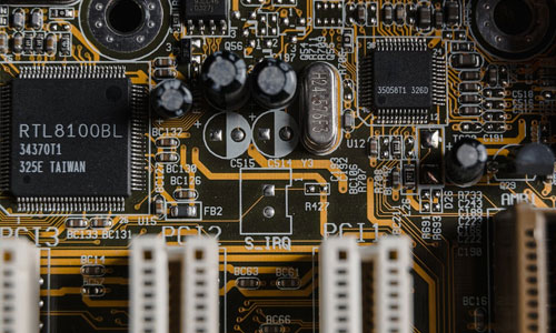
FMW34CP001-40 is listed in the RF Directional Couplers range at ChipApex. The manufacturer field lists Fairview Microwave. Its product description is 40 DB WR-34…
Read More
FMW34CP001-40 is listed in the RF Directional Couplers range at ChipApex. The manufacturer field lists Fairview Microwave. Its product description is 40 DB WR-34…
Read More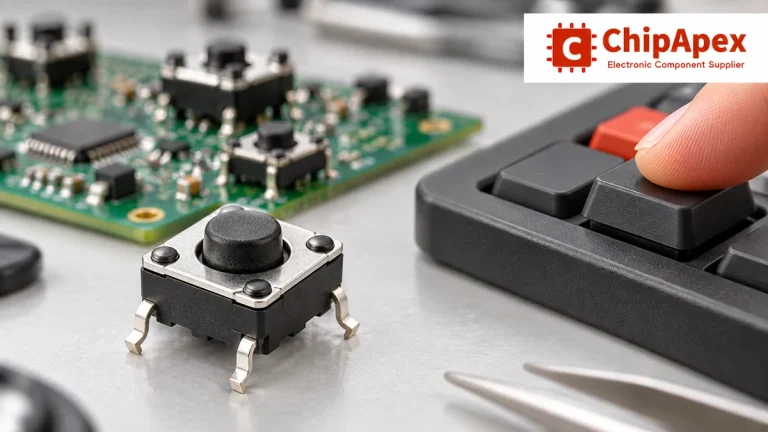
Choose tactile switches by operating force, travel, actuator height, footprint and lifetime. Check debounce, sealing and the assembled button mechanism.
Read More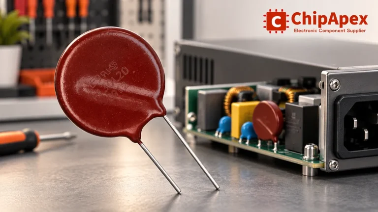
Select MOV varistors by continuous voltage, clamping behavior, surge waveform and repetition. Check thermal disconnection, fuse coordination and replacements.
Read More
FMW34CP001-40 is listed in the RF Directional Couplers range at ChipApex. The manufacturer field lists Fairview Microwave. Its product description is 40 DB WR-34…
Read More
Learn how a diode conducts, how to identify anode and cathode, and when to choose rectifier, TVS, Zener or photodiode types for a circuit.
Read More
The activity of extra discounts on wholesale prices is in full swing…
Please fill in your contact information and we will send you the latest wholesale price list.





