 ChipApex | Global Electronic Components Supplier

SEARCH
Search Product
Search Post
— IC芯片 | 连接器 | 传感器 | 被动器件 —
Search productSearch post
— IC芯片 | 连接器 | 传感器 | 被动器件 —
Consult the customer manager about the wholesale price.
consultation hotline:86-132-6715-2157
email:[email protected]
Contact the product manager for consultation. One-stop consultation is available.
Do you want a lower wholesale price? Please send us your inquiry and we will reply immediately.
MBR1545CTHE3/45 is listed in the Diode Arrays range at ChipApex. The manufacturer field lists Vishay General Semiconductor - Diodes Division. Its product description is DIODE ARR SCHOT 45V 7.5A TO2203. Review the specifications below when checking this part for your BOM.
The MBR1545CTHE3/45 is a dual common cathode Schottky rectifier manufactured by Vishay General Semiconductor. It features a TO-220AB package with a maximum repetitive peak reverse voltage of 45 V and a total maximum average forward rectified current of 15 A (7.5 A per diode). The device exhibits a low forward voltage drop, ranging from 0.57 V to 0.84 V depending on the current and temperature conditions. It supports a peak forward surge current of 150 A per diode and operates within a junction temperature range of -65 °C to +150 °C.
Verify the specific ordering suffix against official documentation to confirm compliance with RoHS standards and material categorization requirements. Confirm that the component meets the necessary whisker test classifications. Ensure the procurement channel sources genuine Vishay products to maintain reliability and adherence to specified electrical characteristics.
Select this component when a dual common cathode configuration is required for space-constrained designs utilizing the TO-220AB footprint. Consider its thermal resistance characteristics and derating curves for high ambient temperature environments. Evaluate the forward voltage specifications against system efficiency targets and ensure the 45 V reverse voltage rating aligns with the circuit's peak operating voltages.
This part belongs to the MBR15xxCT series of dual common cathode Schottky rectifiers designed for general-purpose rectification. The E3 suffix indicates RoHS compliance and matte tin plating. The /45 designation specifies the 45 V voltage rating variant within the family, distinguishing it from other voltage options like the 60 V variant.
Vishay MBR1560CT-E3/45
The maximum thermal resistance from junction to ambient is 60 °C/W, while the junction-to-case thermal resistance is 3.0 °C/W.
At 7.5 A, the forward voltage decreases from 0.75 V at 25 °C to 0.57 V at 125 °C. At 15 A, it drops from 0.84 V at 25 °C to 0.72 V at 125 °C.
Yes, the leads are matte tin plated and solderable per J-STD-002 and JESD 22-B102 standards, supporting a maximum solder bath temperature of 275 °C for 10 seconds.
Explore related parts through Rectifiers, Diodes, Discrete Semiconductor Products, all product categories.
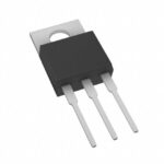 MBR1545CTHE3/45
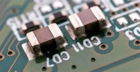
MBR1545CTHE3/45 is listed in the Diode Arrays range at ChipApex. The manufacturer field lists Vishay General Semiconductor - Diodes Division. Its product description is…
Read More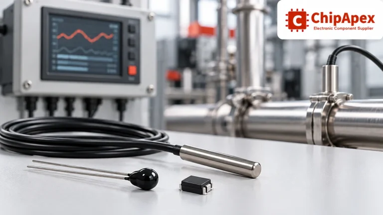
Compare thermistors, RTDs, thermocouples and temperature ICs. Learn how range, accuracy, response, interfaces and mounting affect component selection.
Read More
MBR1545CTHE3/45 is listed in the Diode Arrays range at ChipApex. The manufacturer field lists Vishay General Semiconductor - Diodes Division. Its product description is…
Read More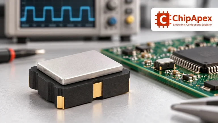
Compare RC, crystal and MEMS oscillator circuits. Check ppm, jitter, load capacitance, startup margin and output compatibility before choosing a clock source.
Read More
MBR1545CTHE3/45 is listed in the Diode Arrays range at ChipApex. The manufacturer field lists Vishay General Semiconductor - Diodes Division. Its product description is…
Read More
MBR1545CTHE3/45 is listed in the Diode Arrays range at ChipApex. The manufacturer field lists Vishay General Semiconductor - Diodes Division. Its product description is…
Read More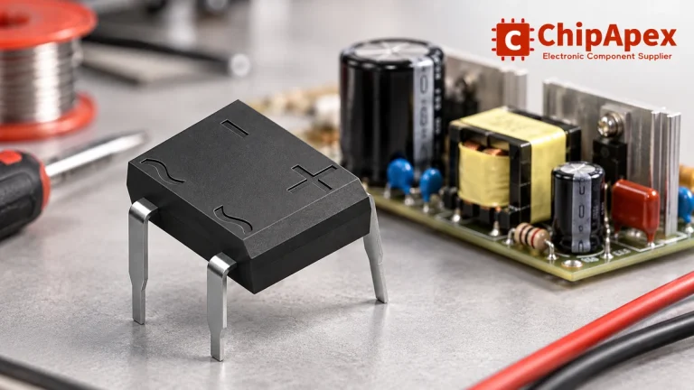
Select a bridge rectifier by reverse voltage, capacitor charging current, startup surge and cooling. Work through a stated DC voltage and ripple example.
Read More
MBR1545CTHE3/45 is listed in the Diode Arrays range at ChipApex. The manufacturer field lists Vishay General Semiconductor - Diodes Division. Its product description is…
Read More
MBR1545CTHE3/45 is listed in the Diode Arrays range at ChipApex. The manufacturer field lists Vishay General Semiconductor - Diodes Division. Its product description is…
Read More
MBR1545CTHE3/45 is listed in the Diode Arrays range at ChipApex. The manufacturer field lists Vishay General Semiconductor - Diodes Division. Its product description is…
Read More
MBR1545CTHE3/45 is listed in the Diode Arrays range at ChipApex. The manufacturer field lists Vishay General Semiconductor - Diodes Division. Its product description is…
Read More
Understand how a comparator switches at a voltage threshold, why hysteresis prevents chatter, and which output and input specs matter.
Read More
The activity of extra discounts on wholesale prices is in full swing…
Please fill in your contact information and we will send you the latest wholesale price list.





