 ChipApex | Global Electronic Components Supplier

SEARCH
Search Product
Search Post
— IC芯片 | 连接器 | 传感器 | 被动器件 —
Search productSearch post
— IC芯片 | 连接器 | 传感器 | 被动器件 —
Consult the customer manager about the wholesale price.
consultation hotline:86-132-6715-2157
email:[email protected]
Contact the product manager for consultation. One-stop consultation is available.
Do you want a lower wholesale price? Please send us your inquiry and we will reply immediately.
SN74LVC125APWRE4 is listed in the Buffers, Drivers, Receivers, Transceivers range at ChipApex. The manufacturer field lists Texas Instruments. Its product description is IC BUF NON-INVERT 3.6V 14TSSOP. Review the specifications below when checking this part for your BOM.
The SN74LVC125APWRE4 is a quadruple bus buffer gate with 3-state outputs manufactured by Texas Instruments. It operates from 1.65V to 3.6V and features independent output-enable inputs for each buffer. The device accepts input voltages up to 5.5V, enabling voltage translation in mixed 3.3V/5V systems. It is housed in a TSSOP-14 package and supports operating temperatures from -40°C to 85°C and -40°C to 125°C. Propagation delay is specified at a maximum of 4.8ns at 3.3V.
Verify the specific suffix 'E4' indicates environmental compliance or manufacturing origin as defined by Texas Instruments documentation. Confirm the TSSOP-14 package type matches the design footprint requirements. Ensure the operating temperature range meets the application's thermal constraints. Cross-reference the datasheet revision date to confirm current specifications.
Select this component when a quadruple bus buffer with independent control is required. It is suitable for applications needing voltage translation between 3.3V and 5V logic levels. Consider the TSSOP-14 package for surface-mount assembly. Verify that the 3-state output capability aligns with the bus architecture design.
This part belongs to the SN74LVC125A family of quadruple bus buffer gates. The 'PW' suffix denotes the TSSOP package, while 'RE4' typically signifies tape and reel packaging with specific environmental attributes. It is part of Texas Instruments' LVC logic series designed for low-voltage applications.
SN74LVC125APWR
The inputs accept voltages up to 5.5V, allowing the device to be driven by 5V devices while operating on a lower VCC supply such as 3.3V.
Each output is disabled (high-impedance state) when its associated Output Enable (OE) input is high. When OE is low, the gate passes data from the A input to the Y output.
Explore related parts through Logic, Integrated Circuits (ICs), all product categories, ChipApex homepage.
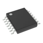 SN74LVC125APWRE4

SN74LVC125APWRE4 is listed in the Buffers, Drivers, Receivers, Transceivers range at ChipApex. The manufacturer field lists Texas Instruments. Its product description is IC BUF…
Read More
Understand how a comparator switches at a voltage threshold, why hysteresis prevents chatter, and which output and input specs matter.
Read More
SN74LVC125APWRE4 is listed in the Buffers, Drivers, Receivers, Transceivers range at ChipApex. The manufacturer field lists Texas Instruments. Its product description is IC BUF…
Read More
Understand tactile switches, PCB and keyboard differences, four-pin wiring, debounce, force, travel and replacement checks for reliable control inputs.
Read More
SN74LVC125APWRE4 is listed in the Buffers, Drivers, Receivers, Transceivers range at ChipApex. The manufacturer field lists Texas Instruments. Its product description is IC BUF…
Read More
Learn what data acquisition means, from sensors and conditioning to sampling and storage. Review channel timing, wiring, calibration and data quality.
Read More
SN74LVC125APWRE4 is listed in the Buffers, Drivers, Receivers, Transceivers range at ChipApex. The manufacturer field lists Texas Instruments. Its product description is IC BUF…
Read More
Choose an ADC converter by resolution, sample rate, noise and input design. Review practical tradeoffs and prepare component requirements for ChipApex.
Read More
SN74LVC125APWRE4 is listed in the Buffers, Drivers, Receivers, Transceivers range at ChipApex. The manufacturer field lists Texas Instruments. Its product description is IC BUF…
Read MoreSN74LVC125APWRE4 is listed in the Buffers, Drivers, Receivers, Transceivers range at ChipApex. The manufacturer field lists Texas Instruments. Its product description is IC BUF…
Read More
See how a MEMS gyroscope measures angular rate, why its angle estimate drifts, and which range, noise, interface and temperature specs to compare.
Read More
Compare Hall, shunt, current transformer and Rogowski sensing. Check AC/DC capability, accuracy, isolation, heat and response before selecting a sensor.
Read More
The activity of extra discounts on wholesale prices is in full swing…
Please fill in your contact information and we will send you the latest wholesale price list.





