ChipApex | Global Electronic Components Supplier

SEARCH
Search Product
Search Post
— IC芯片 | 连接器 | 传感器 | 被动器件 —
Search productSearch post
— IC芯片 | 连接器 | 传感器 | 被动器件 —
Consult the customer manager about the wholesale price.
consultation hotline:86-132-6715-2157
email:[email protected]
Contact the product manager for consultation. One-stop consultation is available.
Do you want a lower wholesale price? Please send us your inquiry and we will reply immediately.
ADS5444HFG/EM is listed in the Analog To Digital Converters (ADC) range at ChipApex. The manufacturer field lists Texas Instruments. Its product description is IC ADC 13BIT PIPELINED 84CFP. Review the specifications below when checking this part for your BOM.
The ADS5444HFG/EM is an evaluation module (EVM) designed for the ADS5444 analog-to-digital converter. It provides a platform for evaluating the ADC under various signal, reference, and supply conditions. The EVM features two analog input paths: one using THS9001 amplifiers and another AC-coupled path. A single-ended clock input is converted to differential at the device input. Digital outputs are accessed via a high-density Samtec header, with a breakout board supporting touchless probing by Agilent and Tektronix logic analyzers. Power is supplied through banana jack sockets for separate analog and digital rails.
Verify that the specific order corresponds to the ADS5444HFG/EM evaluation module variant. Confirm compatibility with the intended ADC device within the ADS5440/44/63/74 family by checking jumper configurations. Ensure handling follows engineering development standards due to the open construction and electrostatic discharge risks associated with evaluation hardware.
Select this module specifically for evaluating the ADS5444 device characteristics. Note that the EVM supports multiple devices in the ADS5440/44/63/74 family; verify jumper settings (J20, J21) to match the target component. Consider the available input paths (balun vs. amplifier) when planning signal source integration for testing requirements.
This evaluation module is part of the ADS5440/44/63/74 EVM series documented in User's Guide SLAU194A. It serves as a development tool for Texas Instruments' high-speed data converters. The module allows engineers to assess ADC performance without designing custom PCB layouts initially, facilitating rapid prototyping and validation of system-level specifications.
No direct replacement part numbers are documented for this specific evaluation module. For different ADC families, distinct EVMs are required. Verify if the ADS5440, ADS5463, or ADS5474 variants require specific jumper adjustments on this same board rather than seeking a different module.
The single-ended clock input applied to connector J17 is converted into a differential signal using a Coilcraft WBC4-1W transformer with an impedance ratio of 4.
Default operation requires three supplies: 5 V for the ADC analog supply, 3.3 V for the ADC analog supply, and 3.3 V for the ADC digital buffer supply, connected via separate banana jack sockets.
Yes, the EVM layout supports migration between these devices. Jumper J20 must be configured to short pins 1–2 for ADS5440/44 or pins 2–3 for ADS5463/74 to select the appropriate digital output buffer voltage.
Explore related parts through Data Acquisition, Integrated Circuits (ICs), all product categories, ChipApex homepage.
 ADS5444HFG/EM
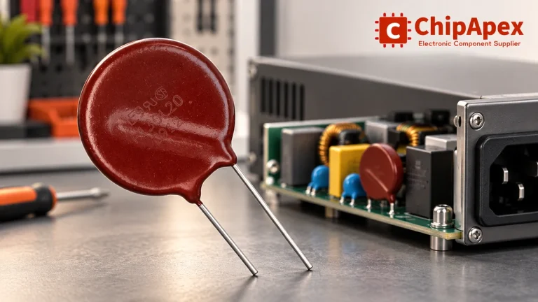
Select MOV varistors by continuous voltage, clamping behavior, surge waveform and repetition. Check thermal disconnection, fuse coordination and replacements.
Read More
ADS5444HFG/EM is listed in the Analog To Digital Converters (ADC) range at ChipApex. The manufacturer field lists Texas Instruments. Its product description is IC…
Read More
Compare Pt100 and Pt1000 RTDs, two-, three- and four-wire connections, excitation and self-heating. Build an error budget from element to reported temperature.
Read More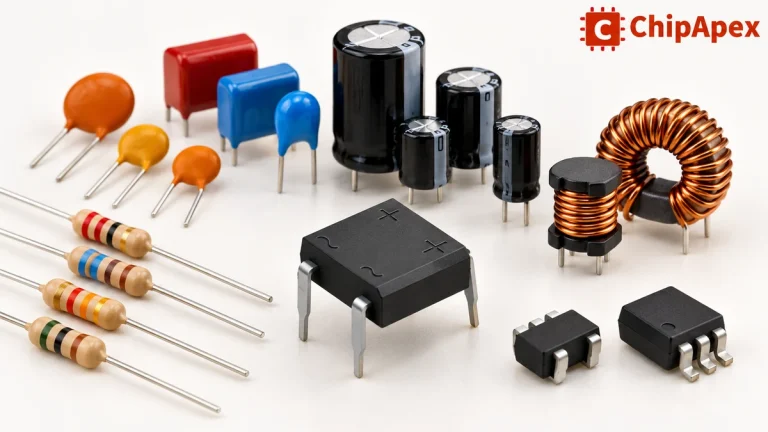
Explore electronic component types, functions, packages and datasheets. Learn selection, replacement and BOM checks before ordering parts for your PCB.
Read More
ADS5444HFG/EM is listed in the Analog To Digital Converters (ADC) range at ChipApex. The manufacturer field lists Texas Instruments. Its product description is IC…
Read More
ADS5444HFG/EM is listed in the Analog To Digital Converters (ADC) range at ChipApex. The manufacturer field lists Texas Instruments. Its product description is IC…
Read More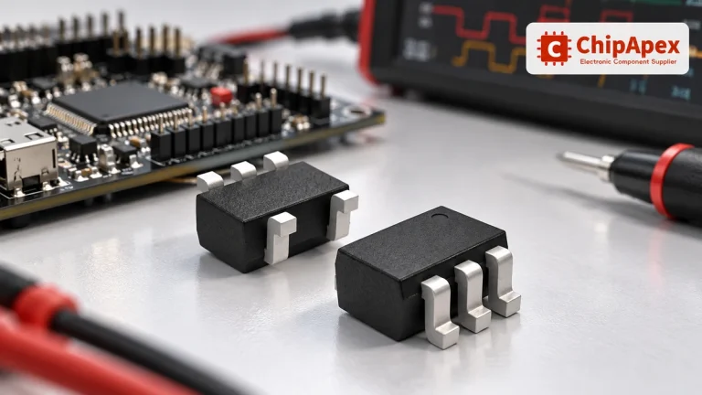
Choose logic inverter ICs by thresholds, supply, output drive and delay. Compare standard and Schmitt-trigger inputs, power sequencing and replacement checks.
Read More
ADS5444HFG/EM is listed in the Analog To Digital Converters (ADC) range at ChipApex. The manufacturer field lists Texas Instruments. Its product description is IC…
Read More
ADS5444HFG/EM is listed in the Analog To Digital Converters (ADC) range at ChipApex. The manufacturer field lists Texas Instruments. Its product description is IC…
Read More
ADS5444HFG/EM is listed in the Analog To Digital Converters (ADC) range at ChipApex. The manufacturer field lists Texas Instruments. Its product description is IC…
Read More
ADS5444HFG/EM is listed in the Analog To Digital Converters (ADC) range at ChipApex. The manufacturer field lists Texas Instruments. Its product description is IC…
Read More
Learn how rectifiers convert AC to DC, compare half-wave and bridge circuits, and select voltage, current, recovery and thermal ratings for your design.
Read More
The activity of extra discounts on wholesale prices is in full swing…
Please fill in your contact information and we will send you the latest wholesale price list.