 ChipApex | Global Electronic Components Supplier
DG441DY+
Search Product
Search Post
— IC芯片 | 连接器 | 传感器 | 被动器件 —
Search productSearch post
— IC芯片 | 连接器 | 传感器 | 被动器件 —
Consult the customer manager about the wholesale price.
consultation hotline:86-132-6715-2157
email:[email protected]
Contact the product manager for consultation. One-stop consultation is available.
Do you want a lower wholesale price? Please send us your inquiry and we will reply immediately.
The DG441DY+ is a quad, single-pole/single-throw (SPST) analog switch manufactured by Analog Devices Inc./Maxim Integrated. It features four normally closed switches in a 16-pin Narrow SO package with an operating temperature range of -40°C to +85°C. The device operates from a single +10V to +30V supply or bipolar ±4.5V to ±20V supplies. Key electrical parameters include a maximum on-resistance of 85Ω, on-resistance matching of 4Ω max, and on-resistance flatness of 9Ω max. Turn-on time is typically 90ns (max 250ns), and turn-off time is typically 120ns (max 170ns). Charge injection is limited to 10pC max, and off-leakage current is less than 5nA at +85°C.
Verify the specific ordering suffix 'DY+' corresponds to the 16-pin Narrow SOIC package and the -40°C to +85°C industrial temperature grade. Confirm that the lead-free designation matches project requirements. Ensure the component source provides valid traceability documentation for the Analog Devices/Maxim Integrated manufacturer identification.
Select this component when a quad SPST configuration with normally closed logic is required. The narrow SO package is appropriate for surface-mount designs needing space efficiency. Verify that the 85Ω maximum on-resistance meets the system's voltage drop constraints. Ensure the bipolar or single-supply voltage ranges align with the available power rails in the target application circuit.
This part belongs to the DG441/DG442 family of improved analog switches. The DG441 variant specifically utilizes normally closed switches, whereas the DG442 uses normally open switches. Both share identical pinouts and electrical characteristics, differing only in their default switch state logic. The redesign offers better matching and lower leakage compared to legacy industry-standard versions.
Direct pin-compatible replacements within the same family include the DG442DY+, which functions as the normally open counterpart. Other variants in the series such as DG441DJ+ offer the same electrical specifications but utilize a Plastic DIP package instead of the Narrow SO format.
The DG441 contains four normally closed switches, while the DG442 contains four normally open switches. All other electrical characteristics and pin configurations are identical.
The guaranteed on-resistance flatness of 9Ω max ensures that the resistance variation across the specified analog signal range is minimized, maintaining signal integrity without significant distortion.
Yes, the device can operate with unbalanced supplies, such as +24V and -5V, provided the difference between V+ and V- does not exceed +44V.
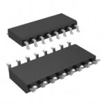 DG441DY+
The activity of extra discounts on wholesale prices is in full swing…
Please fill in your contact information and we will send you the latest wholesale price list.





