 ChipApex | Global Electronic Components Supplier

SEARCH
Search Product
Search Post
— IC芯片 | 连接器 | 传感器 | 被动器件 —
Search productSearch post
— IC芯片 | 连接器 | 传感器 | 被动器件 —
Consult the customer manager about the wholesale price.
consultation hotline:86-132-6715-2157
email:[email protected]
Contact the product manager for consultation. One-stop consultation is available.
Do you want a lower wholesale price? Please send us your inquiry and we will reply immediately.
MC10H641FN is listed in the Clock Buffers, Drivers range at ChipApex. The manufacturer field lists onsemi. Its product description is IC CLK BUFFER 1:9 65MHZ 28PLCC. Review the specifications below when checking this part for your BOM.
The MC10H641FN is a single-supply, low skew translating 1:9 clock driver manufactured by onsemi. It converts PECL inputs to TTL outputs within the MECL 10H logic family. The device operates on a single +5.0 V supply with separate ECL and TTL power pins. Key electrical parameters include a maximum propagation delay of 6.36 ns from input D to output Q at 85°C, a maximum operating frequency of 65 MHz, and a typical power supply current of 30 mA. It features a latch mechanism controlled by LEN and EN pins, housed in a PLCC-28 package.
Verify component authenticity through authorized channels as counterfeit risks exist for legacy parts. Confirm RoHS compliance status if required, noting that the 'G' suffix indicates Pb-Free packaging while standard versions may not be compliant. Ensure proper handling procedures are followed due to moisture sensitivity classification.
Select this component when interfacing high-speed PECL sources with TTL loads requiring minimal skew. Verify that the application voltage range aligns with the specified 4.75 V to 5.25 V limits. Consider thermal management requirements given the 30 mA supply current and PLCC-28 package thermal characteristics.
This part belongs to the MC10H/100H641 series, designed for optimal signal flow and electrical performance using the PLCC-28 package. It serves as a functional equivalent to popular ECLinPS translators, offering improved noise margins and propagation delays compared to older standard logic devices.
Direct pin-compatible replacements within the same family include MC10H641FNG (Pb-Free version). Cross-family alternatives require verification of voltage levels and pinout compatibility.
The VBB pin provides a positive ECL reference voltage output. For single-ended input use, it should be connected to the D input and bypassed with a 0.01 µF capacitor.
LEN controls the latch transparency; when LOW, the latch is transparent. When EN is HIGH, all outputs are forced LOW. Both are positive ECL inputs.
The maximum input frequency is specified as 65 MHz into a 50 pF load, ensuring minimum output swing levels.
Explore related parts through Clock/Timing, Integrated Circuits (ICs), all product categories, ChipApex homepage.
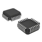 MC10H641FN
MC10H641FN is listed in the Clock Buffers, Drivers range at ChipApex. The manufacturer field lists onsemi. Its product description is IC CLK BUFFER 1:9…
Read More
MC10H641FN is listed in the Clock Buffers, Drivers range at ChipApex. The manufacturer field lists onsemi. Its product description is IC CLK BUFFER 1:9…
Read More
MC10H641FN is listed in the Clock Buffers, Drivers range at ChipApex. The manufacturer field lists onsemi. Its product description is IC CLK BUFFER 1:9…
Read More
MC10H641FN is listed in the Clock Buffers, Drivers range at ChipApex. The manufacturer field lists onsemi. Its product description is IC CLK BUFFER 1:9…
Read More
MC10H641FN is listed in the Clock Buffers, Drivers range at ChipApex. The manufacturer field lists onsemi. Its product description is IC CLK BUFFER 1:9…
Read More
MC10H641FN is listed in the Clock Buffers, Drivers range at ChipApex. The manufacturer field lists onsemi. Its product description is IC CLK BUFFER 1:9…
Read More
MC10H641FN is listed in the Clock Buffers, Drivers range at ChipApex. The manufacturer field lists onsemi. Its product description is IC CLK BUFFER 1:9…
Read More
MC10H641FN is listed in the Clock Buffers, Drivers range at ChipApex. The manufacturer field lists onsemi. Its product description is IC CLK BUFFER 1:9…
Read More
MC10H641FN is listed in the Clock Buffers, Drivers range at ChipApex. The manufacturer field lists onsemi. Its product description is IC CLK BUFFER 1:9…
Read More
MC10H641FN is listed in the Clock Buffers, Drivers range at ChipApex. The manufacturer field lists onsemi. Its product description is IC CLK BUFFER 1:9…
Read More
MC10H641FN is listed in the Clock Buffers, Drivers range at ChipApex. The manufacturer field lists onsemi. Its product description is IC CLK BUFFER 1:9…
Read More
Explore electronic component types, functions, packages and datasheets. Learn selection, replacement and BOM checks before ordering parts for your PCB.
Read More
The activity of extra discounts on wholesale prices is in full swing…
Please fill in your contact information and we will send you the latest wholesale price list.




