ChipApex | Global Electronic Components Supplier

SEARCH
Search Product
Search Post
— IC芯片 | 连接器 | 传感器 | 被动器件 —
Search productSearch post
— IC芯片 | 连接器 | 传感器 | 被动器件 —
Consult the customer manager about the wholesale price.
consultation hotline:86-132-6715-2157
email:[email protected]
Contact the product manager for consultation. One-stop consultation is available.
Do you want a lower wholesale price? Please send us your inquiry and we will reply immediately.
SN74HC20N is listed in the Inverter Gates range at ChipApex. The manufacturer field lists Texas Instruments. Its product description is IC GATE NAND 2CH 4-INP 14DIP. Review the specifications below when checking this part for your BOM.
The SN74HC20N is a Texas Instruments dual 4-input NAND gate in the HC logic family. It operates on a supply voltage of 2 V to 6 V and supports an operating temperature range from -40°C to +85°C. The device features buffered standard CMOS inputs and balanced push-pull outputs capable of driving up to 10 LSTTL loads. Propagation delay ranges from 11 ns to 140 ns depending on voltage, with a typical power dissipation capacitance of 25 pF per gate.
Verify the specific ordering suffix against the manufacturer's current package option addendum to confirm the physical package type and lead finish. Ensure the selected variant matches the required thermal resistance and pin configuration for the target PCB layout. Confirm RoHS compliance status if environmental regulations apply to the assembly process.
Select this component when designing systems requiring multiple independent 4-input NAND logic functions within a single integrated circuit. The HC series offers significant power reduction compared to older LSTTL technologies while maintaining compatible fanout capabilities. Verify that input signal transition times fall within recommended limits to avoid excessive shoot-through current consumption during switching events.
This device belongs to the SNx4HC20 family of high-speed CMOS logic devices manufactured by Texas Instruments. It provides a cost-effective solution for implementing complex combinational logic in digital systems. The PDIP-14 package facilitates through-hole mounting for prototyping and industrial applications requiring robust mechanical connections.
SN74HC20D (SOIC package)
Unused inputs must not be left floating. They should be terminated directly to VCC or ground, or connected via pull-up/pull-down resistors to establish a defined logic state.
Input signals must have fast edge rates as defined in the Recommended Operating Conditions. Slow edge rates can cause oscillations and damaging shoot-through current due to the standard CMOS input structure.
Explore related parts through Logic, Integrated Circuits (ICs), all product categories, ChipApex homepage.
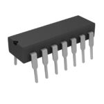 SN74HC20N
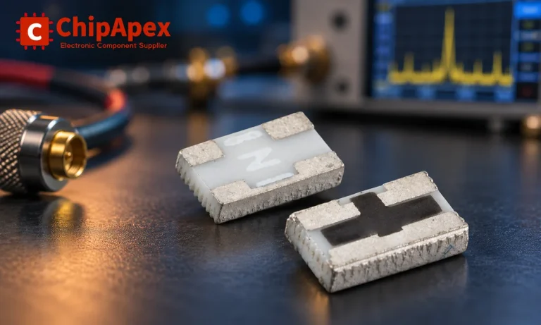
Understand RF attenuator dB values, fixed and programmable types, impedance, power limits and noise tradeoffs before choosing parts for an RF signal path.
Read More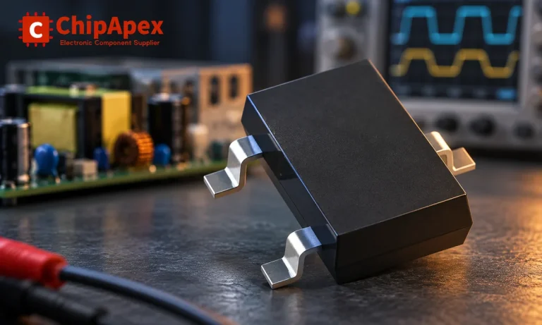
Learn how rectifiers convert AC to DC, compare half-wave and bridge circuits, and select voltage, current, recovery and thermal ratings for your design.
Read More
Learn how to use ferrite beads for noise filtering. Check impedance, DC bias, placement, resonance and load-step behavior before selecting a part.
Read More
SN74HC20N is listed in the Inverter Gates range at ChipApex. The manufacturer field lists Texas Instruments. Its product description is IC GATE NAND 2CH…
Read More
Understand UART protocol framing, baud rate and electrical interfaces. Learn 8N1 timing, TX/RX wiring, buffering and practical troubleshooting steps.
Read More
SN74HC20N is listed in the Inverter Gates range at ChipApex. The manufacturer field lists Texas Instruments. Its product description is IC GATE NAND 2CH…
Read More
Learn how a pressure transducer converts pressure into voltage, current, or digital output, and compare pressure references and key selection specs.
Read More
Learn how a Zener diode regulates voltage. Calculate resistor current and power, check tolerance and temperature, and distinguish Zener and TVS applications.
Read More
Learn how optical sensing works, compare detection methods, and select sensors by target surface, ambient light, response time and electrical interface.
Read More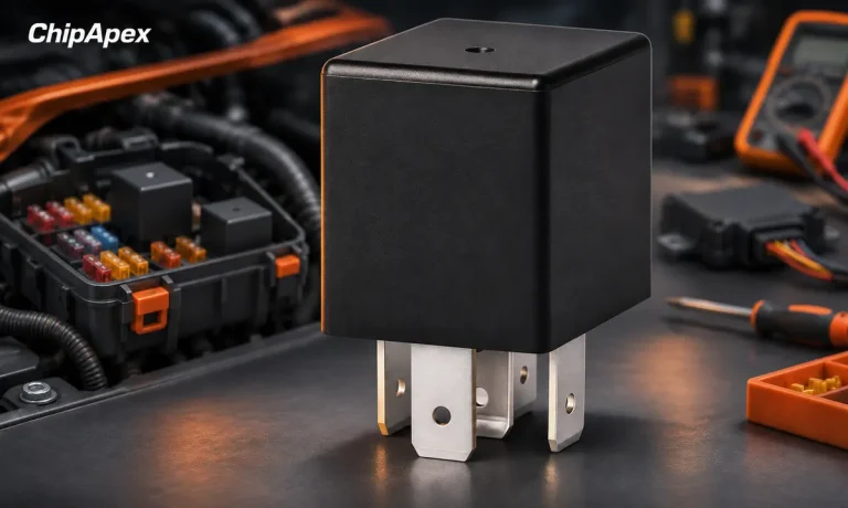
Understand automotive relay terminals, coil suppression and load ratings. Check inrush, socket compatibility and temperature before selecting a replacement.
Read More
SN74HC20N is listed in the Inverter Gates range at ChipApex. The manufacturer field lists Texas Instruments. Its product description is IC GATE NAND 2CH…
Read More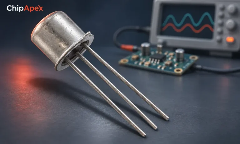
Learn what a transistor does in a circuit. Compare switching and amplification, BJT and MOSFET drive, operating limits and practical component selection.
Read More
The activity of extra discounts on wholesale prices is in full swing…
Please fill in your contact information and we will send you the latest wholesale price list.