ChipApex | Global Electronic Components Supplier

SEARCH
Search Product
Search Post
— IC芯片 | 连接器 | 传感器 | 被动器件 —
Search productSearch post
— IC芯片 | 连接器 | 传感器 | 被动器件 —
Consult the customer manager about the wholesale price.
consultation hotline:86-132-6715-2157
email:[email protected]
Contact the product manager for consultation. One-stop consultation is available.
Do you want a lower wholesale price? Please send us your inquiry and we will reply immediately.
SN74HC32N-P2 is listed in the Inverter Gates range at ChipApex. The manufacturer field lists Texas Instruments. Its product description is IC GATE OR 4CH 2-INP 14DIP. Review the specifications below when checking this part for your BOM.
The SN74HC32N-P2 is a commercial-grade quadruple 2-input positive-OR gate manufactured by Texas Instruments. It operates within a supply voltage range of 2 V to 6 V and supports an operating temperature range from -40°C to +85°C. The device features buffered inputs, balanced CMOS push-pull outputs, and clamp diode structures on all pins. It provides significant power reduction compared to LSTTL logic ICs while supporting fanout up to 10 LSTTL loads.
Verify the specific package type and ordering suffixes against the manufacturer's current orderable addendum. Confirm that the component meets RoHS requirements and check the lead finish specifications. Ensure the selected variant aligns with the required thermal resistance and mounting style for the intended PCB layout.
Select this component when a wide operating voltage range between 2 V and 6 V is required. It is suitable for designs needing low power consumption relative to LSTTL alternatives. Consider the -40°C to +85°C temperature range for commercial applications. Verify input transition rates to prevent oscillations due to slow edge rates.
This device belongs to the SNx4HC32 family of quadruple 2-input OR gates. It is part of the broader HC (High-speed CMOS) logic series designed for general-purpose digital applications. The N designation typically indicates a PDIP package, though other packages like SOIC and SSOP are available within the same functional family.
SN74HC32D
Unused inputs must not be left floating. They should be terminated to either VCC or ground, potentially using a pull-up or pull-down resistor if the input is used intermittently.
A 0.1-μF capacitor is recommended for each VCC terminal, placed physically close to the device to prevent power disturbances.
Explore related parts through Logic, Integrated Circuits (ICs), all product categories, ChipApex homepage.
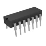 SN74HC32N-P2
Compare Pt100 and Pt1000 RTDs, two-, three- and four-wire connections, excitation and self-heating. Build an error budget from element to reported temperature.
Read More
SN74HC32N-P2 is listed in the Inverter Gates range at ChipApex. The manufacturer field lists Texas Instruments. Its product description is IC GATE OR 4CH…
Read More
Learn how CPLDs implement hardware logic, compare them with FPGAs and MCUs, and check timing, I/O voltage, startup behavior and programming requirements.
Read More
Explore electronic component types, functions, packages and datasheets. Learn selection, replacement and BOM checks before ordering parts for your PCB.
Read More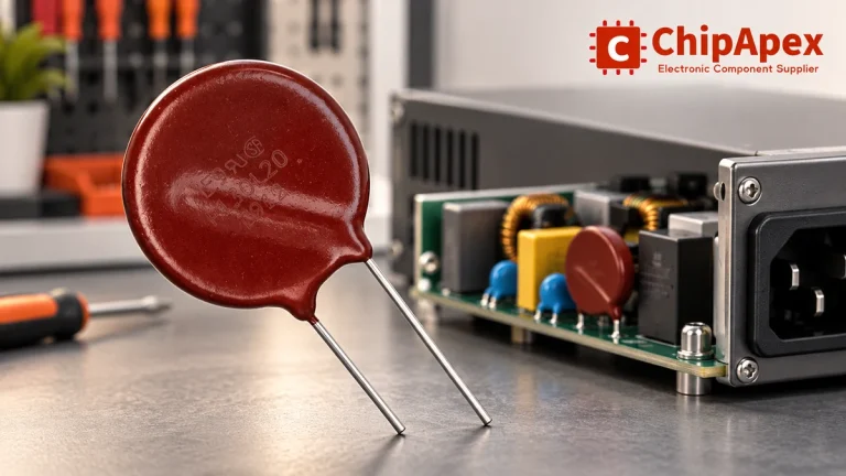
Select MOV varistors by continuous voltage, clamping behavior, surge waveform and repetition. Check thermal disconnection, fuse coordination and replacements.
Read More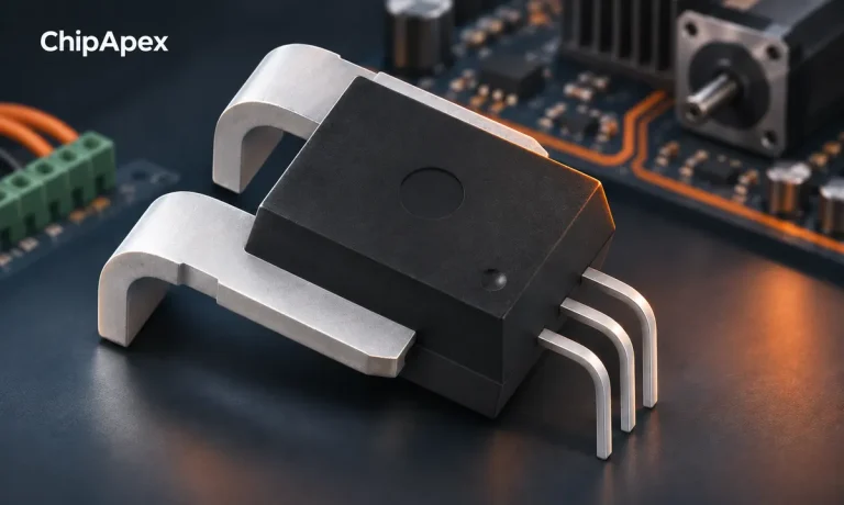
Compare Hall, shunt, current transformer and Rogowski sensing. Check AC/DC capability, accuracy, isolation, heat and response before selecting a sensor.
Read More
SN74HC32N-P2 is listed in the Inverter Gates range at ChipApex. The manufacturer field lists Texas Instruments. Its product description is IC GATE OR 4CH…
Read More
SN74HC32N-P2 is listed in the Inverter Gates range at ChipApex. The manufacturer field lists Texas Instruments. Its product description is IC GATE OR 4CH…
Read More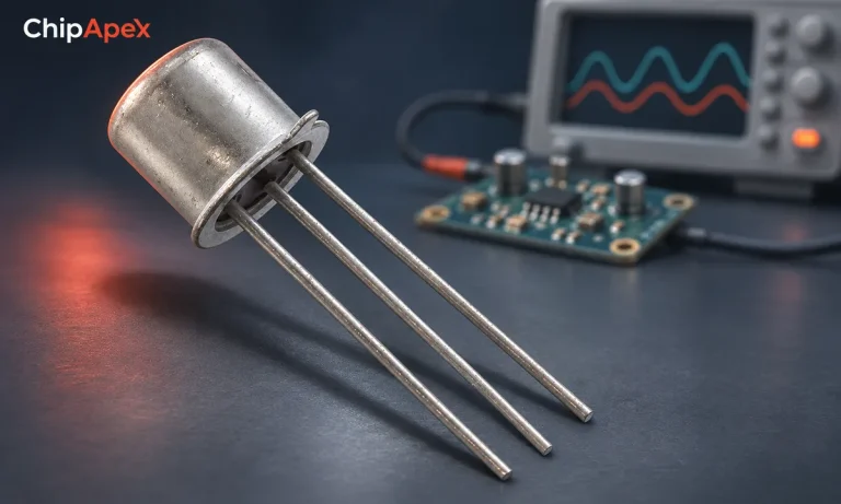
Learn what a transistor does in a circuit. Compare switching and amplification, BJT and MOSFET drive, operating limits and practical component selection.
Read More
Learn how a Zener diode regulates voltage. Calculate resistor current and power, check tolerance and temperature, and distinguish Zener and TVS applications.
Read More
Understand motor controller types, driver functions, startup current, feedback and braking. Use practical checks to match control electronics to your motor.
Read More
Compare gas sensor technologies, cross-sensitivity and calibration needs. Define the gas, range and environment before choosing a sensing component.
Read More
The activity of extra discounts on wholesale prices is in full swing…
Please fill in your contact information and we will send you the latest wholesale price list.