ChipApex | Global Electronic Components Supplier

SEARCH
Search Product
Search Post
— IC芯片 | 连接器 | 传感器 | 被动器件 —
Search productSearch post
— IC芯片 | 连接器 | 传感器 | 被动器件 —
Consult the customer manager about the wholesale price.
consultation hotline:86-132-6715-2157
email:[email protected]
Contact the product manager for consultation. One-stop consultation is available.
Do you want a lower wholesale price? Please send us your inquiry and we will reply immediately.
MA4L032-1056 is listed in the RF Diode range at ChipApex. The manufacturer field lists MACOM Technology Solutions. Its product description is RF DIODE PIN 50V 4W ODS-1056. Review the specifications below when checking this part for your BOM.
The MA4L032-1056 is a gold-doped silicon PIN limiter diode from the MA4L series, packaged in the ODS-1056 surface mount configuration. It features a breakdown voltage of 30V minimum and 50V maximum at 10 µA. Junction capacitance is typically 0.12 pF at 10 V reverse bias (max 0.18 pF) and 0.20 pF at 0 V (max 0.20 pF). Series resistance is 2.50 Ω at 10 mA forward current and 500 MHz. The device has a carrier lifetime of 15 ns with an I-region thickness of 3 µm (1.5 mils). Nominal high signal performance at 9.4 GHz includes a recovery time of 34 ns, 44 dBm incident peak power limiting, and 4 dB CW input power.
Verify the specific ordering suffix against the manufacturer's official datasheet to confirm the ODS-1056 package style. Ensure that the base part number MA4L032 corresponds to the required gold-doped die characteristics. Confirm RoHS compliance status through the latest product documentation before procurement.
Select this component when a balance between moderate breakdown voltage and fast recovery time is required. The gold doping provides lower recovery time compared to non-gold variants. Consider the 2.50 Ω series resistance and 0.20 pF junction capacitance for impedance matching in shunt configurations within the specified frequency range.
This device belongs to the MACOM MA4L, MADL, and MADP series of silicon PIN limiter diodes. These devices are engineered for small and medium I-region lengths to handle high signal applications. The series offers various package options including discrete dies and assembled surface mount packages like the ODS-1056.
MA4L032-134 (Chip)
Gold-doped devices, such as the MA4L032, are designed for lower recovery time. Non-gold doped devices are available for applications requiring lower flat leakage.
Maximum series resistance is measured at 500 MHz and represents the total diode resistance, calculated as the sum of chip junction resistance and package ohmic resistance.
The absolute maximum mounting temperature is +320°C for a duration of 10 seconds.
Explore related parts through Diodes, Discrete Semiconductor Products, all product categories, ChipApex homepage.
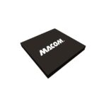 MA4L032-1056

MA4L032-1056 is listed in the RF Diode range at ChipApex. The manufacturer field lists MACOM Technology Solutions. Its product description is RF DIODE PIN…
Read More
MA4L032-1056 is listed in the RF Diode range at ChipApex. The manufacturer field lists MACOM Technology Solutions. Its product description is RF DIODE PIN…
Read More
MA4L032-1056 is listed in the RF Diode range at ChipApex. The manufacturer field lists MACOM Technology Solutions. Its product description is RF DIODE PIN…
Read More
MA4L032-1056 is listed in the RF Diode range at ChipApex. The manufacturer field lists MACOM Technology Solutions. Its product description is RF DIODE PIN…
Read More
MA4L032-1056 is listed in the RF Diode range at ChipApex. The manufacturer field lists MACOM Technology Solutions. Its product description is RF DIODE PIN…
Read More
MA4L032-1056 is listed in the RF Diode range at ChipApex. The manufacturer field lists MACOM Technology Solutions. Its product description is RF DIODE PIN…
Read More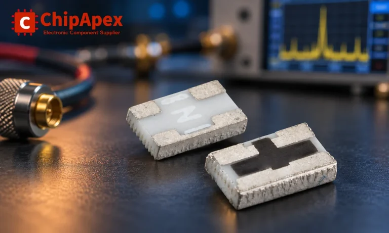
Understand RF attenuator dB values, fixed and programmable types, impedance, power limits and noise tradeoffs before choosing parts for an RF signal path.
Read More
MA4L032-1056 is listed in the RF Diode range at ChipApex. The manufacturer field lists MACOM Technology Solutions. Its product description is RF DIODE PIN…
Read More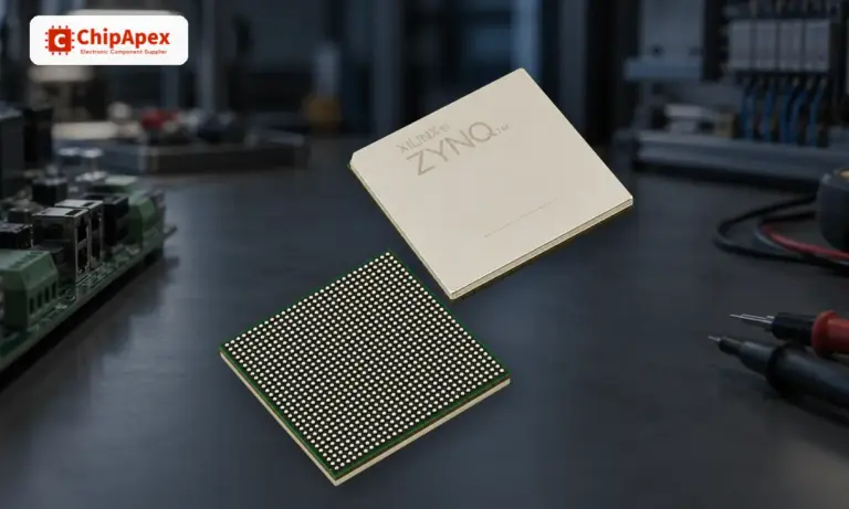
Learn what an integrated circuit is, how ICs work, the main types and the specs to check before choosing a part for your design…
Read More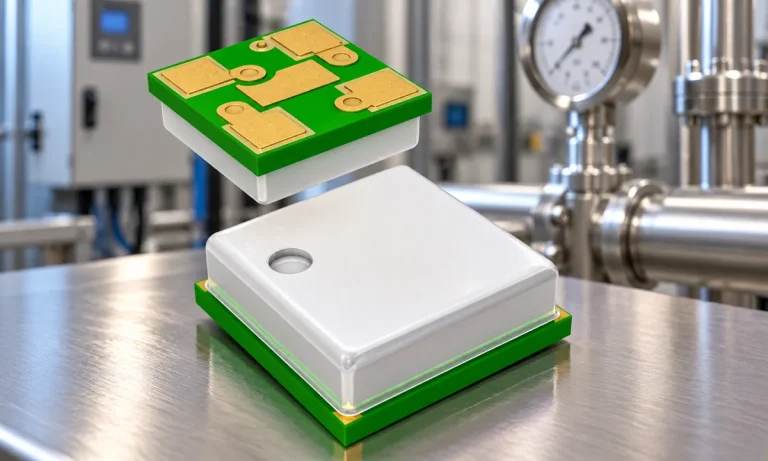
Learn how a pressure transducer converts pressure into voltage, current, or digital output, and compare pressure references and key selection specs.
Read More
MA4L032-1056 is listed in the RF Diode range at ChipApex. The manufacturer field lists MACOM Technology Solutions. Its product description is RF DIODE PIN…
Read More
MA4L032-1056 is listed in the RF Diode range at ChipApex. The manufacturer field lists MACOM Technology Solutions. Its product description is RF DIODE PIN…
Read More
The activity of extra discounts on wholesale prices is in full swing…
Please fill in your contact information and we will send you the latest wholesale price list.