ChipApex | Global Electronic Components Supplier

SEARCH
Search Product
Search Post
— IC芯片 | 连接器 | 传感器 | 被动器件 —
Search productSearch post
— IC芯片 | 连接器 | 传感器 | 被动器件 —
Consult the customer manager about the wholesale price.
consultation hotline:86-132-6715-2157
email:[email protected]
Contact the product manager for consultation. One-stop consultation is available.
Do you want a lower wholesale price? Please send us your inquiry and we will reply immediately.
MADP-030015-13140P is listed in the RF Diode range at ChipApex. The manufacturer field lists MACOM Technology Solutions. Its product description is DIODE,HMIC,PIN SURMOUNT. Review the specifications below when checking this part for your BOM.
The MADP-030015-13140P is a silicon PIN diode from the SURMOUNT family, utilizing MACOM's HMIC process. It features a 15 µm intrinsic region and an ODS-1314 surface mount package with a 0603 outline. Key electrical specifications include a maximum reverse voltage of 115 V, a typical capacitance of 0.78 pF at -40 V and 1 GHz, and a series resistance ranging from 0.38 to 0.49 Ω at +70 mA and 1 GHz. The device supports a forward current of 500 mA, operates between -55°C and +125°C, and has a thermal resistance of 13 °C/W.
Verify the specific ordering suffix against official documentation before procurement. The 'P' suffix indicates a reel packaging format containing 3000 pieces. Confirm that the required quantity aligns with the factory packaging unit to avoid partial reel issues or unnecessary inventory holding costs during the purchasing phase.
Select this component when a low parasitic inductance design is critical for RF performance. The 15 µm I-region length provides a balance between capacitance and carrier lifetime. Ensure the application environment stays within the specified operating temperature range and that the mounting substrate allows for effective thermal dissipation given the 13 °C/W thermal resistance rating.
This part belongs to the MAPD-017015 & MAPD-030015 SURMOUNT family. It shares identical physical dimensions with the MADP-017015-1314 variant but differs in electrical characteristics due to the specific doping profile associated with the 30015 designation. Both devices utilize the same ODS-1314 case style and HMIC fabrication technology.
The MADP-017015-13140P is a related variant within the same datasheet. While it shares the same package and mechanical outline, its electrical parameters such as capacitance and series resistance differ. Verify if the specific impedance matching requirements of the circuit can accommodate the lower capacitance values of the 017015 model before substitution.
Connections to the backside are facilitated by making the pedestal sidewalls electrically conductive, with selective backside metallization applied to produce the surface mount device.
For hard substrates, hot gas die bonding is preferred. A vacuum tip pick-up tool and a downward force of 60 to 100 grams should be applied while applying heat near the circuit trace and diode mounting pad.
The topside is fully encapsulated with silicon nitride and includes an additional polymer layer designed to provide scratch and impact protection for the junction and anode air-bridge.
Explore related parts through Diodes, Discrete Semiconductor Products, all product categories, ChipApex homepage.
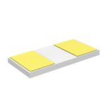 MADP-030015-13140P
MADP-030015-13140P is listed in the RF Diode range at ChipApex. The manufacturer field lists MACOM Technology Solutions. Its product description is DIODE,HMIC,PIN SURMOUNT. Review…
Read More
MADP-030015-13140P is listed in the RF Diode range at ChipApex. The manufacturer field lists MACOM Technology Solutions. Its product description is DIODE,HMIC,PIN SURMOUNT. Review…
Read More
Choose logic inverter ICs by thresholds, supply, output drive and delay. Compare standard and Schmitt-trigger inputs, power sequencing and replacement checks.
Read More
Understand how oscillators generate timing signals, how they differ from crystals, and which frequency, output and stability specs matter when choosing one.
Read More
MADP-030015-13140P is listed in the RF Diode range at ChipApex. The manufacturer field lists MACOM Technology Solutions. Its product description is DIODE,HMIC,PIN SURMOUNT. Review…
Read MoreMADP-030015-13140P is listed in the RF Diode range at ChipApex. The manufacturer field lists MACOM Technology Solutions. Its product description is DIODE,HMIC,PIN SURMOUNT. Review…
Read More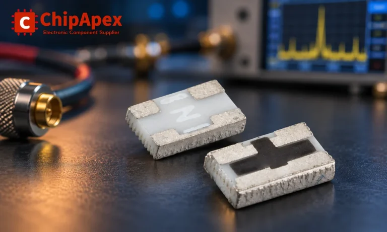
Understand RF attenuator dB values, fixed and programmable types, impedance, power limits and noise tradeoffs before choosing parts for an RF signal path.
Read More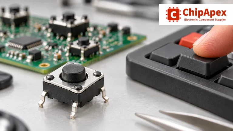
Understand tactile switches, PCB and keyboard differences, four-pin wiring, debounce, force, travel and replacement checks for reliable control inputs.
Read More
MADP-030015-13140P is listed in the RF Diode range at ChipApex. The manufacturer field lists MACOM Technology Solutions. Its product description is DIODE,HMIC,PIN SURMOUNT. Review…
Read More
MADP-030015-13140P is listed in the RF Diode range at ChipApex. The manufacturer field lists MACOM Technology Solutions. Its product description is DIODE,HMIC,PIN SURMOUNT. Review…
Read More
MADP-030015-13140P is listed in the RF Diode range at ChipApex. The manufacturer field lists MACOM Technology Solutions. Its product description is DIODE,HMIC,PIN SURMOUNT. Review…
Read More
MADP-030015-13140P is listed in the RF Diode range at ChipApex. The manufacturer field lists MACOM Technology Solutions. Its product description is DIODE,HMIC,PIN SURMOUNT. Review…
Read More
The activity of extra discounts on wholesale prices is in full swing…
Please fill in your contact information and we will send you the latest wholesale price list.