ChipApex | Global Electronic Components Supplier

SEARCH
Search Product
Search Post
— IC芯片 | 连接器 | 传感器 | 被动器件 —
Search productSearch post
— IC芯片 | 连接器 | 传感器 | 被动器件 —
Consult the customer manager about the wholesale price.
consultation hotline:86-132-6715-2157
email:[email protected]
Contact the product manager for consultation. One-stop consultation is available.
Do you want a lower wholesale price? Please send us your inquiry and we will reply immediately.
SN74HC20DRG4 is listed in the Inverter Gates range at ChipApex. The manufacturer field lists Texas Instruments. Its product description is IC GATE NAND 2CH 4-INP 14SOIC. Review the specifications below when checking this part for your BOM.
The SN74HC20DRG4 is a dual 4-input positive-NAND gate in the HC logic family, housed in a 14-pin SOIC package. It operates within a supply voltage range of 2 V to 6 V and supports an operating temperature range from -40°C to +85°C. The device features buffered inputs and balanced CMOS push-pull outputs capable of driving up to 10 LSTTL loads. Propagation delay ranges from 11 ns to 140 ns depending on voltage and temperature.
Verify the specific ordering suffix against the manufacturer's latest Package Option Addendum to confirm production status and lead finish specifications. Ensure the component matches the required thermal resistance metrics for the SOIC (D) package variant. Confirm RoHS compliance and moisture sensitivity level ratings prior to integration into the assembly process.
Select this component when a dual 4-input NAND function is required within standard CMOS logic families. It is suitable for designs needing wide voltage operation between 2 V and 6 V. Consider the propagation delay characteristics relative to the system clock speed and ensure the output drive capability meets the load requirements without exceeding absolute maximum ratings.
This device belongs to the SNx4HC20 series of dual 4-input NAND gates manufactured by Texas Instruments. It is part of the broader HC logic family, designed to offer performance improvements over earlier TTL technologies while maintaining compatibility. The DRG4 designation indicates a tape-and-reel packaging format for surface-mount assembly.
SN74HC20DR
Unused inputs must not be left floating. They should be terminated to either VCC or ground using pull-up or pull-down resistors to prevent undefined operational states and excessive current consumption.
To ensure optimal performance, the capacitive load at the output should be less than or equal to 70 pF. Larger loads may require a series resistor to limit output current.
Explore related parts through Logic, Integrated Circuits (ICs), all product categories, ChipApex homepage.
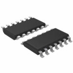 SN74HC20DRG4
Understand how an LDO regulates voltage. Check dropout, noise, PSRR, output capacitors and heat before selecting a low-dropout regulator for your circuit.
Read More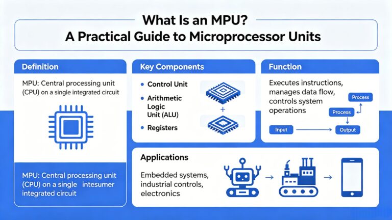
SN74HC20DRG4 is listed in the Inverter Gates range at ChipApex. The manufacturer field lists Texas Instruments. Its product description is IC GATE NAND 2CH…
Read More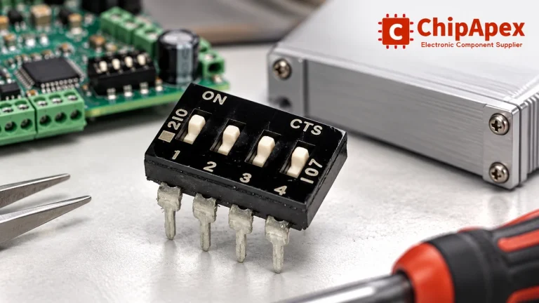
Choose a DIP switch by contact type, coded positions, footprint and signal ratings. Check logic polarity, assembly conditions and PCB configuration behavior.
Read MoreSN74HC20DRG4 is listed in the Inverter Gates range at ChipApex. The manufacturer field lists Texas Instruments. Its product description is IC GATE NAND 2CH…
Read More
SN74HC20DRG4 is listed in the Inverter Gates range at ChipApex. The manufacturer field lists Texas Instruments. Its product description is IC GATE NAND 2CH…
Read More
SN74HC20DRG4 is listed in the Inverter Gates range at ChipApex. The manufacturer field lists Texas Instruments. Its product description is IC GATE NAND 2CH…
Read More
SN74HC20DRG4 is listed in the Inverter Gates range at ChipApex. The manufacturer field lists Texas Instruments. Its product description is IC GATE NAND 2CH…
Read More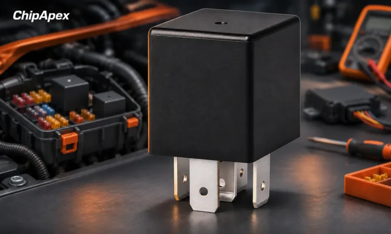
Understand automotive relay terminals, coil suppression and load ratings. Check inrush, socket compatibility and temperature before selecting a replacement.
Read More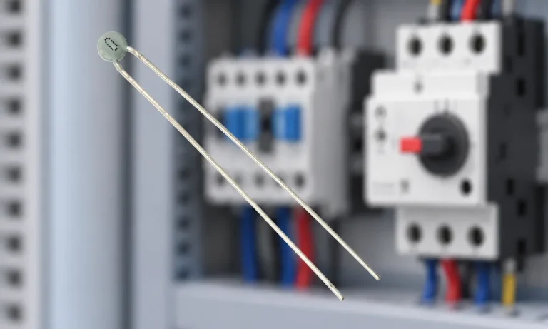
Learn why PTC resistance rises with temperature, how it differs from NTC, and which ratings matter for sensing and protection.
Read More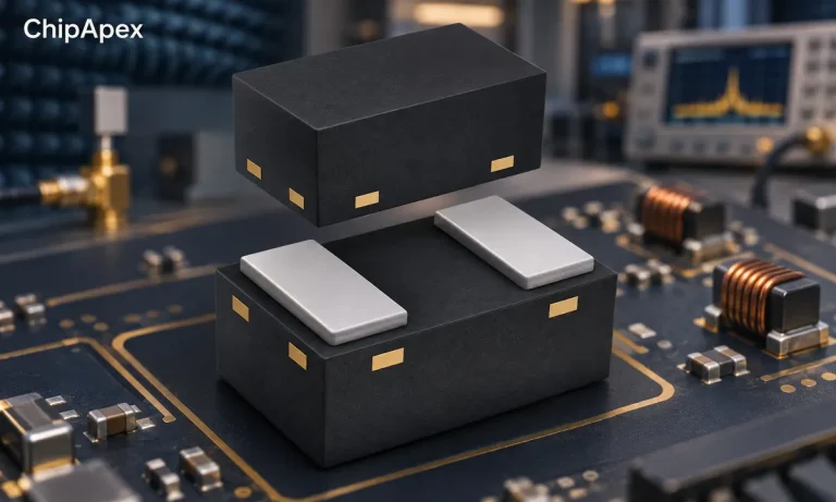
Compare variable capacitor types and varactor tuning. Understand capacitance-voltage curves, Q, bias and LC resonance before choosing a component.
Read More
Choose a vibration sensor for machine monitoring. Compare sensing methods, bandwidth, noise and mounting, then define the signal-chain requirements.
Read More
SN74HC20DRG4 is listed in the Inverter Gates range at ChipApex. The manufacturer field lists Texas Instruments. Its product description is IC GATE NAND 2CH…
Read More
The activity of extra discounts on wholesale prices is in full swing…
Please fill in your contact information and we will send you the latest wholesale price list.