ChipApex | Global Electronic Components Supplier

SEARCH
Search Product
Search Post
— IC芯片 | 连接器 | 传感器 | 被动器件 —
Search productSearch post
— IC芯片 | 连接器 | 传感器 | 被动器件 —
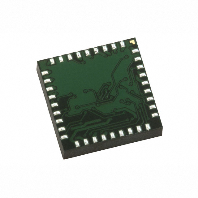
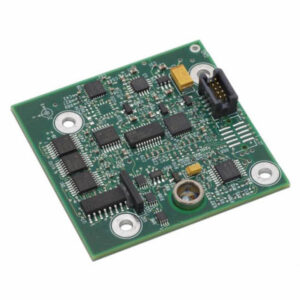
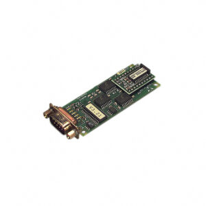
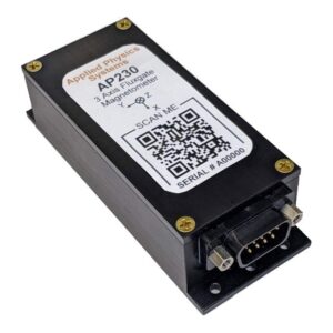
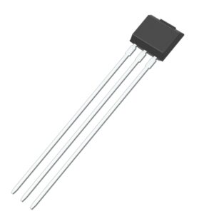
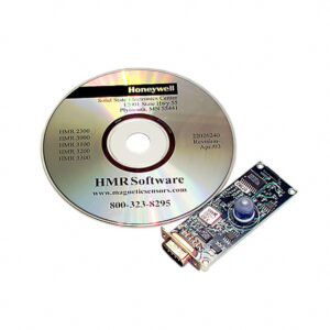
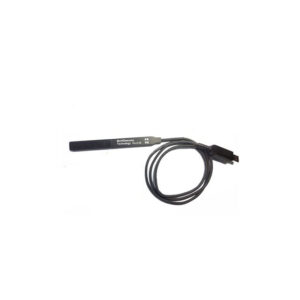
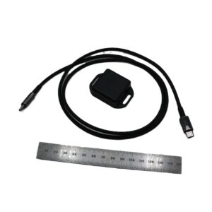
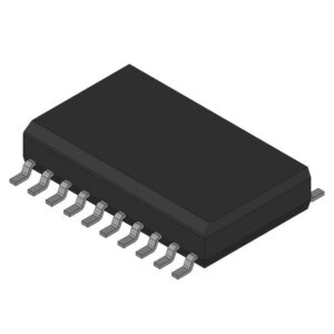
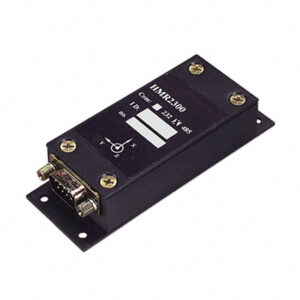
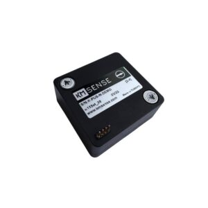
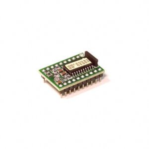
Compass and Magnetic Field Module sensors are devices designed to detect and respond to the presence of a magnetic field. Items in this family are designed for dead reckoning, digital compass, or a digital magnetometer in the X, Y, Z axis. They are used for measuring heading, pitch and roll, and strength or direction with a measuring range of ±0.9 gauss, ±1 gauss, ±180µT, ±2 gauss, or ±700 mgauss.
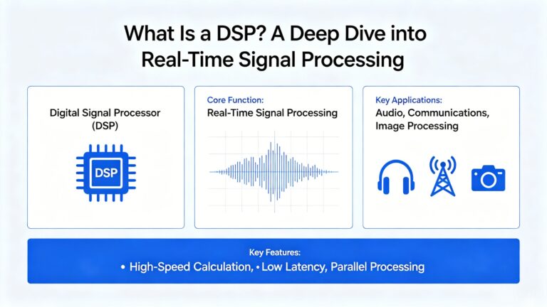
In the embedded world, general-purpose CPUs are great at running operating systems, and MCUs excel at logic control. But when you need to process…
Read More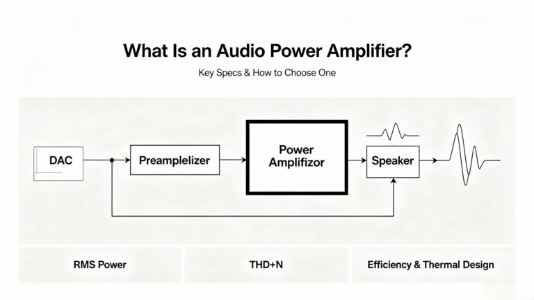
Every audio power amplifier design starts with the same fundamental challenge: converting a low-voltage line-level signal into the high-current drive required by a reactive…
Read More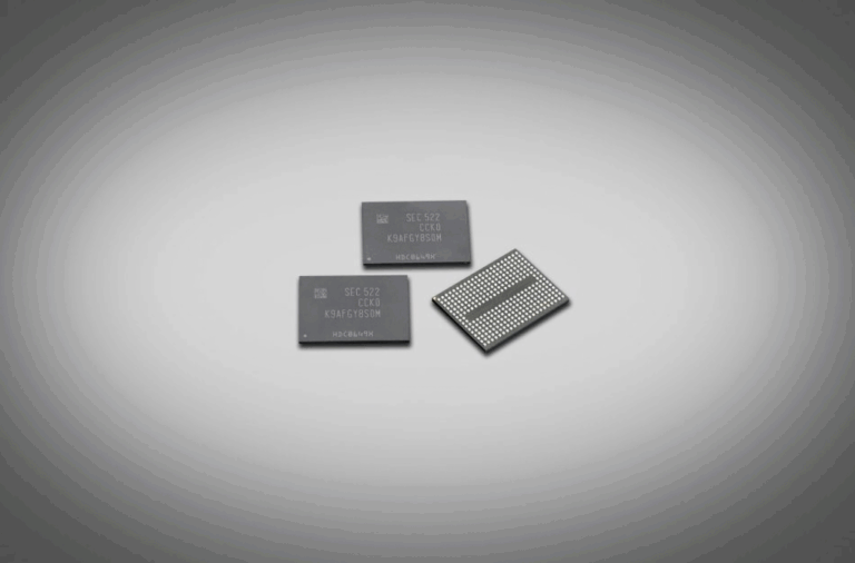
Date: May 13, 2026 The global memory industry is facing an unprecedented supply crunch in legacy MLC NAND Flash. Leading manufacturers including Samsung Electronics…
Read More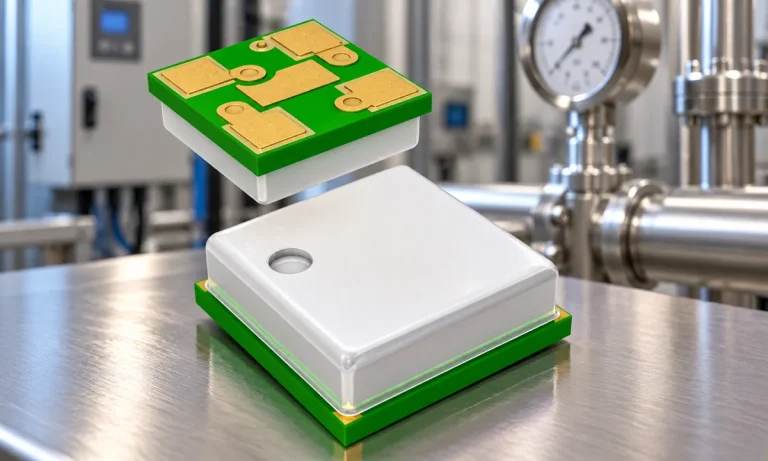
Learn how a pressure transducer converts pressure into voltage, current, or digital output, and compare pressure references and key selection specs.
Read More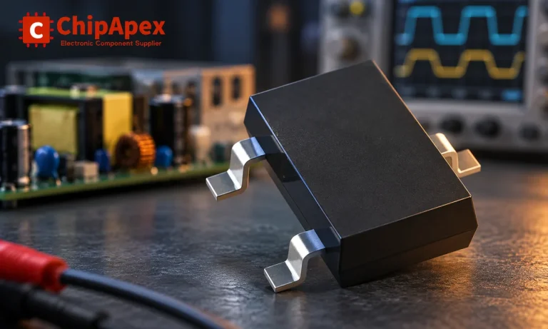
Learn how rectifiers convert AC to DC, compare half-wave and bridge circuits, and select voltage, current, recovery and thermal ratings for your design.
Read More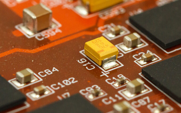
The global electronics industry is facing an escalating shortage of tantalum capacitors, a critical passive component, as surging demand from AI servers, automotive electronics,…
Read More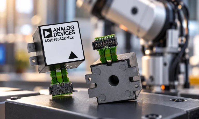
Learn what an IMU measures, how accelerometers and gyroscopes work together, why orientation estimates drift, and what to compare.
Read More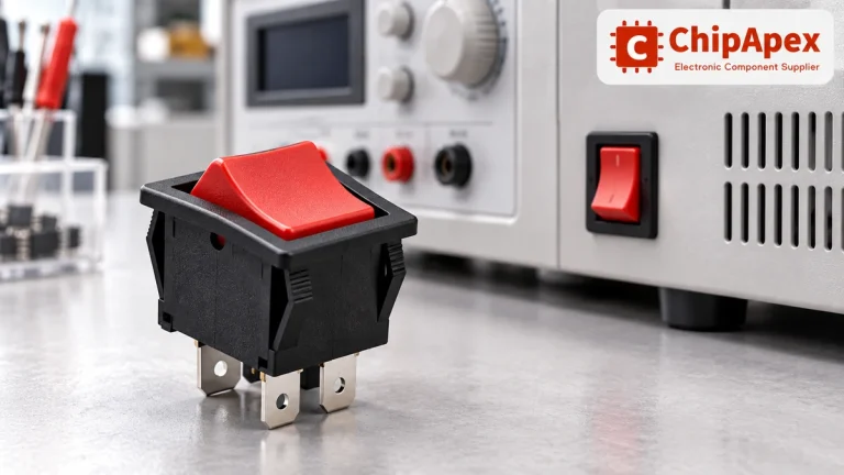
Choose a rocker switch by AC/DC ratings, contact arrangement, illumination, panel fit and sealing. Get practical checks for engineering and component sourcing.
Read More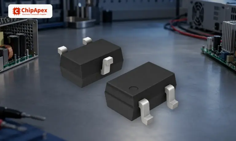
Learn how a diode conducts, how to identify anode and cathode, and when to choose rectifier, TVS, Zener or photodiode types for a circuit.
Read More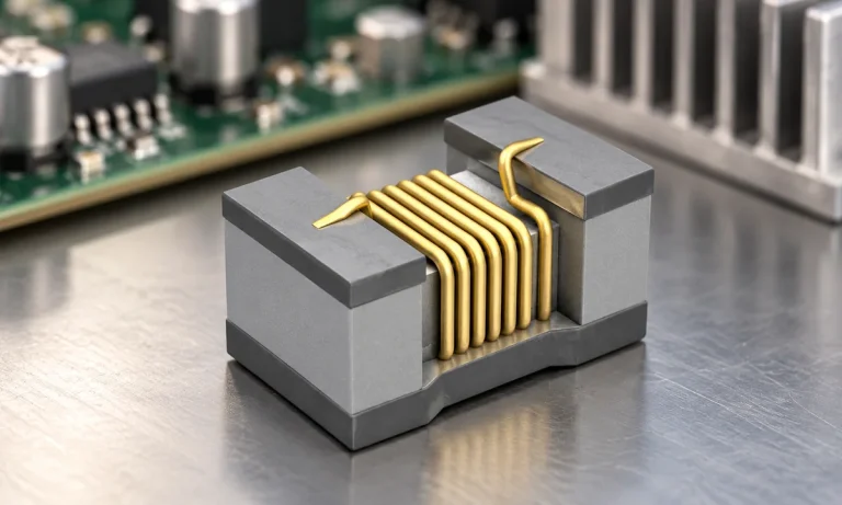
See when an inductor behaves linearly, how DC bias and saturation reduce inductance, and which current and temperature curves to check.
Read More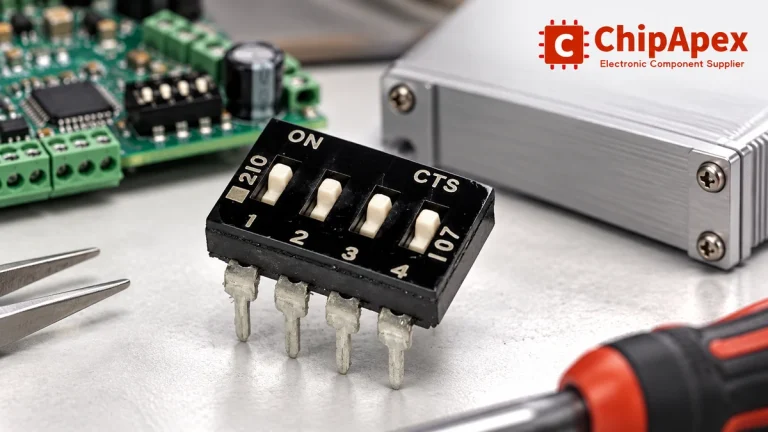
Choose a DIP switch by contact type, coded positions, footprint and signal ratings. Check logic polarity, assembly conditions and PCB configuration behavior.
Read More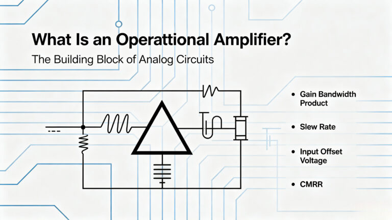
If you’ve spent any time staring at a schematic, you’ve seen the triangle. Two inputs, one output, and a gain symbol that looks deceptively…
Read More
The activity of extra discounts on wholesale prices is in full swing…
Please fill in your contact information and we will send you the latest wholesale price list.