 ChipApex | Global Electronic Components Supplier

SEARCH
Search Product
Search Post
— IC芯片 | 连接器 | 传感器 | 被动器件 —
Search productSearch post
— IC芯片 | 连接器 | 传感器 | 被动器件 —
Consult the customer manager about the wholesale price.
consultation hotline:86-132-6715-2157
email:[email protected]
Contact the product manager for consultation. One-stop consultation is available.
Do you want a lower wholesale price? Please send us your inquiry and we will reply immediately.
MBR10100CS2TR-G1 is listed in the Diode Arrays range at ChipApex. The manufacturer field lists Diodes Incorporated. Its product description is DIODE ARRAY SCHOT 100V 5A TO-263. Review the specifications below when checking this part for your BOM.
The MBR10100CS2TR-G1 is a high voltage dual Schottky rectifier manufactured by Diodes Incorporated. It features a TO-263-2 (D2PAK) surface mount package with tape and reel packing. The device contains two independent diode legs, each rated for a peak repetitive reverse voltage of 100 V and an average rectified forward current of 5 A at +136°C case temperature. The maximum instantaneous forward voltage drop is 0.85 V at +25°C with 5 A current. The component supports a junction temperature range from -55°C to +150°C.
Verify the specific ordering suffix TR indicates tape and reel packaging rather than tube distribution. Confirm the G1 suffix aligns with required environmental compliance standards such as RoHS and Green specifications. Ensure the TO-263-2 package dimensions match the target PCB footprint layout requirements before finalizing procurement orders.
Select this component when designing medium voltage switch mode power supplies requiring low forward voltage drops to minimize conduction losses. The dual leg architecture allows efficient use of space in compact designs. Verify thermal resistance ratings against the expected heat sink or PCB copper area to ensure the junction temperature remains within the specified operating limits under maximum load conditions.
This part belongs to the MBR10100C series of high voltage power Schottky rectifiers from Diodes Incorporated. The series offers multiple package options including through-hole and surface mount variants. The CS2 designation specifically identifies the TO-263-2 surface mount form factor, while the TR suffix denotes the automated tape and reel delivery method for surface mount assembly lines.
MBR10100CS2-G1
The device can withstand a non-repetitive peak surge current of 100 A under half-wave, single phase, 60 Hz conditions applied at rated load.
The maximum instantaneous forward voltage drop decreases from 0.85 V at +25°C to 0.75 V at +125°C when tested with 5 A forward current.
Yes, the datasheet specifies the device is intended for high frequency circuits where low switching losses and low noise are required.
Explore related parts through Rectifiers, Diodes, Discrete Semiconductor Products, all product categories.
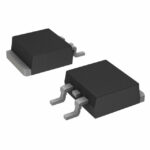 MBR10100CS2TR-G1
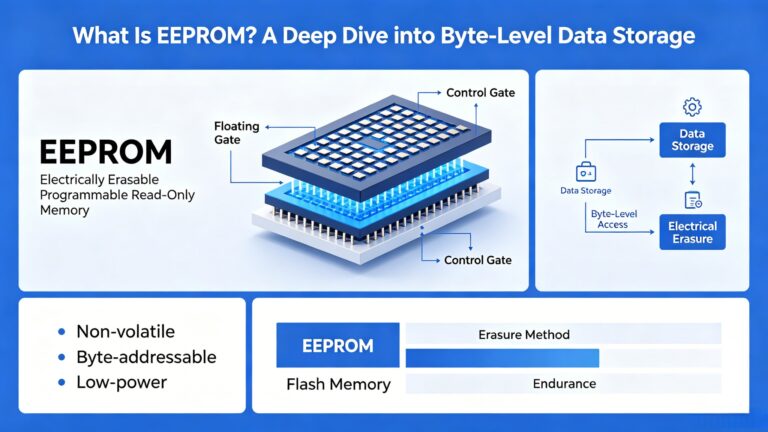
MBR10100CS2TR-G1 is listed in the Diode Arrays range at ChipApex. The manufacturer field lists Diodes Incorporated. Its product description is DIODE ARRAY SCHOT 100V…
Read More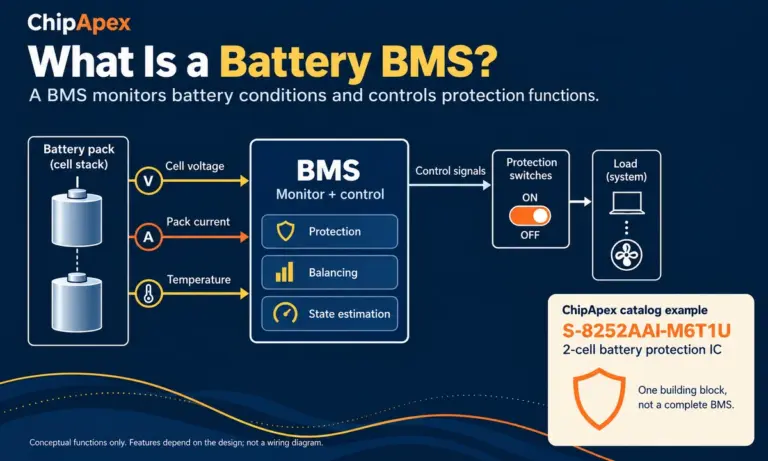
Learn what a battery BMS does, how protection differs from charging, and which pack specifications to check when sourcing BMS components through ChipApex.
Read More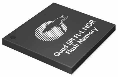
MBR10100CS2TR-G1 is listed in the Diode Arrays range at ChipApex. The manufacturer field lists Diodes Incorporated. Its product description is DIODE ARRAY SCHOT 100V…
Read More
Choose logic inverter ICs by thresholds, supply, output drive and delay. Compare standard and Schmitt-trigger inputs, power sequencing and replacement checks.
Read More
MBR10100CS2TR-G1 is listed in the Diode Arrays range at ChipApex. The manufacturer field lists Diodes Incorporated. Its product description is DIODE ARRAY SCHOT 100V…
Read More
Understand thermal fuse operation, Tf, Th and Tm, electrical ratings and mounting. Check temperature limits and replacement requirements for your design.
Read More
Learn the relay definition, coil and contact operation, NO and NC forms, load ratings and suppression choices. Compare mechanical, reed and solid-state types.
Read More
MBR10100CS2TR-G1 is listed in the Diode Arrays range at ChipApex. The manufacturer field lists Diodes Incorporated. Its product description is DIODE ARRAY SCHOT 100V…
Read More
MBR10100CS2TR-G1 is listed in the Diode Arrays range at ChipApex. The manufacturer field lists Diodes Incorporated. Its product description is DIODE ARRAY SCHOT 100V…
Read More
MBR10100CS2TR-G1 is listed in the Diode Arrays range at ChipApex. The manufacturer field lists Diodes Incorporated. Its product description is DIODE ARRAY SCHOT 100V…
Read More
MBR10100CS2TR-G1 is listed in the Diode Arrays range at ChipApex. The manufacturer field lists Diodes Incorporated. Its product description is DIODE ARRAY SCHOT 100V…
Read More
MBR10100CS2TR-G1 is listed in the Diode Arrays range at ChipApex. The manufacturer field lists Diodes Incorporated. Its product description is DIODE ARRAY SCHOT 100V…
Read More
The activity of extra discounts on wholesale prices is in full swing…
Please fill in your contact information and we will send you the latest wholesale price list.





