 ChipApex | Global Electronic Components Supplier

SEARCH
Search Product
Search Post
— IC芯片 | 连接器 | 传感器 | 被动器件 —
Search productSearch post
— IC芯片 | 连接器 | 传感器 | 被动器件 —
Consult the customer manager about the wholesale price.
consultation hotline:86-132-6715-2157
email:[email protected]
Contact the product manager for consultation. One-stop consultation is available.
Do you want a lower wholesale price? Please send us your inquiry and we will reply immediately.
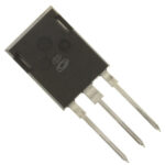
APT5010B2FLLG is listed in the Single FETs, MOSFETs range at ChipApex. The manufacturer field lists Microchip Technology. Its product description is MOSFET N-CH 500V 46A T-MAX. Review the specifications below when checking this part for your BOM.
The APT5010B2FLLG is a Power MOS 7® N-Channel enhancement mode power MOSFET in the T-MAX™ [B2] package. It features a Drain-Source Breakdown Voltage (VDSS) of 500V and a Continuous Drain Current (ID) of 46A at TC = 25°C. The Drain-Source On-State Resistance (RDS(on)) is 0.100 Ohms at VGS = 10V and ID = 23A. Total Power Dissipation (PD) is 520W at TC = 25°C with a linear derating factor of 4.0 W/°C. Operating and Storage Junction Temperature Range (TJ,TSTG) spans from -55 to +150°C.
Verify the specific ordering suffix matches the required package variant, as B2 denotes the T-MAX™ [B2] form factor. Confirm static and dynamic electrical parameters against the official datasheet before integration. Ensure proper electrostatic discharge handling procedures are followed during assembly due to device sensitivity.
Select this component for high-voltage applications requiring low on-state resistance and fast switching characteristics. Evaluate thermal management requirements based on the 520W power dissipation rating and junction-to-case thermal impedance. Consider the 500V breakdown voltage and 46A continuous current limits for circuit design margins.
This part belongs to the Microchip Technology POWER MOS 7® series, representing a generation of low-loss, high-voltage N-Channel enhancement mode power MOSFETs. The series addresses both conduction and switching losses through optimized RDS(ON) and gate charge reduction.
APT5010LFLL shares identical electrical specifications but utilizes the TO-264 (L) package instead of the T-MAX™ [B2] form factor. Verify mechanical footprint compatibility when substituting between these package variants.
The single pulse avalanche energy (EAS) rating is 1600 mJ, starting at an initial junction temperature of +25°C.
At TJ = 25°C, the typical forward voltage is 1.3V at IS = -46A. At TJ = 125°C, it increases to approximately 1.3V under similar conditions, though specific values depend on the operating point.
Explore related parts through FETs, MOSFETs, Transistors, Discrete Semiconductor Products, all product categories.
 APT5010B2FLLG
APT5010B2FLLG is listed in the Single FETs, MOSFETs range at ChipApex. The manufacturer field lists Microchip Technology. Its product description is MOSFET N-CH 500V…
Read More
APT5010B2FLLG is listed in the Single FETs, MOSFETs range at ChipApex. The manufacturer field lists Microchip Technology. Its product description is MOSFET N-CH 500V…
Read More
APT5010B2FLLG is listed in the Single FETs, MOSFETs range at ChipApex. The manufacturer field lists Microchip Technology. Its product description is MOSFET N-CH 500V…
Read More
APT5010B2FLLG is listed in the Single FETs, MOSFETs range at ChipApex. The manufacturer field lists Microchip Technology. Its product description is MOSFET N-CH 500V…
Read More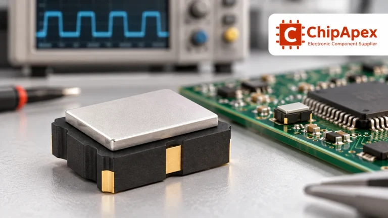
Compare RC, crystal and MEMS oscillator circuits. Check ppm, jitter, load capacitance, startup margin and output compatibility before choosing a clock source.
Read More
APT5010B2FLLG is listed in the Single FETs, MOSFETs range at ChipApex. The manufacturer field lists Microchip Technology. Its product description is MOSFET N-CH 500V…
Read More
APT5010B2FLLG is listed in the Single FETs, MOSFETs range at ChipApex. The manufacturer field lists Microchip Technology. Its product description is MOSFET N-CH 500V…
Read More
APT5010B2FLLG is listed in the Single FETs, MOSFETs range at ChipApex. The manufacturer field lists Microchip Technology. Its product description is MOSFET N-CH 500V…
Read More
APT5010B2FLLG is listed in the Single FETs, MOSFETs range at ChipApex. The manufacturer field lists Microchip Technology. Its product description is MOSFET N-CH 500V…
Read More
APT5010B2FLLG is listed in the Single FETs, MOSFETs range at ChipApex. The manufacturer field lists Microchip Technology. Its product description is MOSFET N-CH 500V…
Read MoreAPT5010B2FLLG is listed in the Single FETs, MOSFETs range at ChipApex. The manufacturer field lists Microchip Technology. Its product description is MOSFET N-CH 500V…
Read More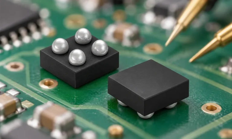
Understand how a comparator switches at a voltage threshold, why hysteresis prevents chatter, and which output and input specs matter.
Read More
The activity of extra discounts on wholesale prices is in full swing…
Please fill in your contact information and we will send you the latest wholesale price list.





